
Environment-friendly drying equipment for bioengineering

A technology of bioengineering and drying equipment, applied in the field of bioengineering, can solve the problems of drying, incomplete drying, and the device cannot achieve drying and environmental protection, and achieves the effect of reducing workload, improving drying efficiency and strong practicability

Pending Publication Date: 2018-09-18
江西省食品发酵研究所
View PDF5 Cites 2 Cited by
  • Summary
  • Abstract
  • Description
  • Claims
  • Application Information

AI Technical Summary

Problems solved by technology

[0003] There are many drying devices in the existing bioengineering, and the materials are usually heated and dried. However, when there are many materials, it is impossible to dry all the materials due to the accumulation of materials, so that part of the materials cannot be dried due to accumulation. Thorough disadvantages; and in the modern conservation-oriented society, the drying of materials in bioengineering needs to achieve the effect of environmental protection, and the existing devices cannot meet the requirements of drying and environmental protection. Therefore, we propose an environmentally friendly drying equipment for bioengineering

Method used

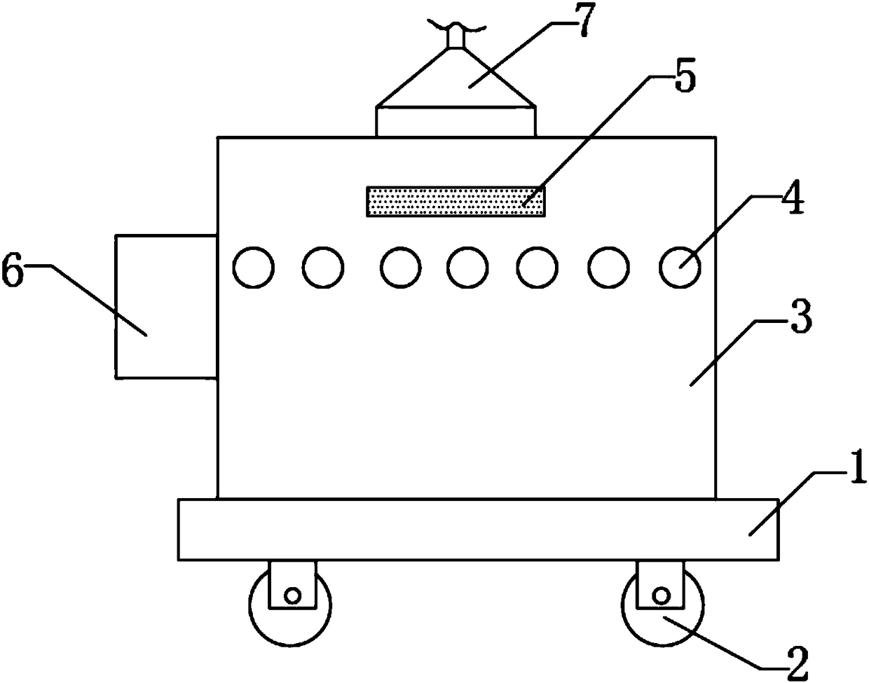
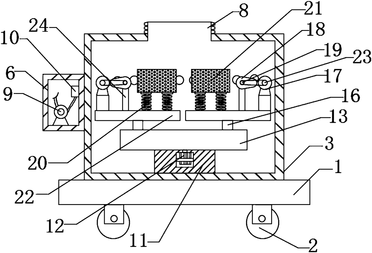
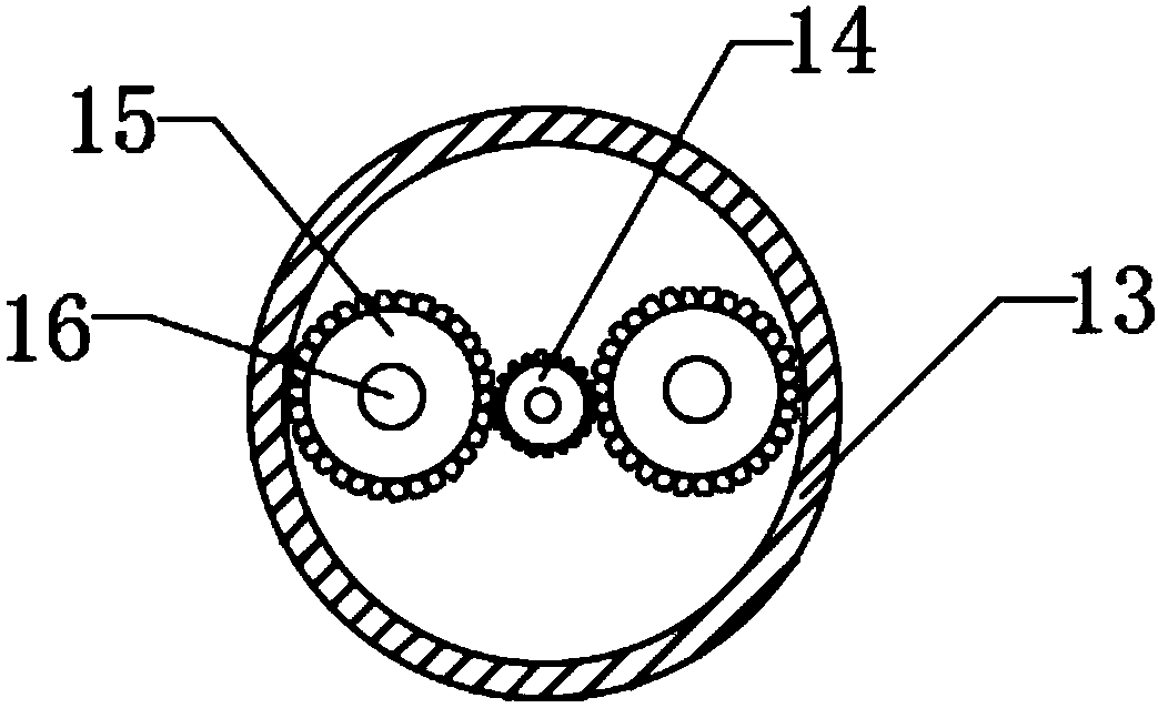

Image

  • Environment-friendly drying equipment for bioengineering
  • Environment-friendly drying equipment for bioengineering
  • Environment-friendly drying equipment for bioengineering

Examples


Embodiment Construction

[0015] Any feature disclosed in this specification, unless specifically stated, can be replaced by other alternative features that are equivalent or have similar purposes. That is, unless expressly stated otherwise, each feature is one example only of a series of equivalent or similar features.

[0016] Such as Figure 1-Figure 3 An environmentally friendly drying equipment for bioengineering is shown, including base 1, self-locking wheel 2, drying box 3, drying hole 4, handle 5, power box 6, suction cover 7, air outlet 8, fan 9, heating Box 10, support base 11, first motor 12, installation box 13, sun gear 14, planetary gear 15, rotating shaft 16, second motor 17, cam 18, driven roller 19, telescopic spring 20, drying basket 21, support plate 22. The driving roller 23 and the fixed rod 24, the top of the base 1 is fixedly connected with a drying box 3, the sides of the drying box 3 are provided with drying holes 4, and the bottom of the inner wall of the drying box 3 is fixe...


PUM


Abstract

The invention discloses environment-friendly drying equipment for bioengineering. The drying equipment comprises a base, a self-locking wheel, a drying box, drying holes, a pull hand, a power box, a suction cover, an air outlet, a fan, a heating box, a supporting base, a first motor, an installation box, a sun gear, planetary gears, rotating shafts, a second motor, a cam, a driven roller, a telescopic spring, a drying basket, a supporting plate, a driving roller and a fixing rod. The drying box is fixedly connected to the top of the base, the drying holes are formed in the side faces of the drying box, the supporting base is fixedly connected to the bottom of the inner wall of the drying box, the first motor is fixedly installed inside the supporting base, the installation box is fixedly connected to the top of the supporting base, an output shaft of the first motor penetrates through the supporting base and the installation box to be fixedly connected with the sun gear, the rotating shafts are symmetrically and rotationally connected to the portions, on the two sides of the sun gear, of the bottom of the inner wall of the supporting base, and the planetary gears are connected to the portions, on the outer sides of the rotating shafts, inside the supporting base. The drying equipment is simple in structure, good in drying effect and environmentally friendly.

Description

technical field [0001] The invention relates to the technical field of bioengineering, in particular to an environment-friendly drying equipment for bioengineering. Background technique [0002] Dryers are commonly used in biological engineering. The dryer is a mechanical device that blows the heated gas to the material to vaporize and escape the moisture in the material to obtain a solid material with a specified moisture content. The dryer can be operated according to the operating process and operating pressure. , heating method and other different characteristics classification. [0003] There are many drying devices in the existing bioengineering, and the materials are usually heated and dried. However, when there are many materials, it is impossible to dry all the materials due to the accumulation of materials, so that part of the materials cannot be dried due to accumulation. Thorough disadvantages; and in the modern conservation-oriented society, the drying of mater...

Claims


Application Information

Patent Timeline
Patent Type & Authority Applications(China)
IPC IPC(8): F26B11/18F26B21/00F26B21/04F26B25/02F26B25/04
CPCF26B11/182F26B21/001F26B21/004F26B21/04F26B25/02F26B25/04Y02P70/10
Inventor 巫小波
Owner 江西省食品发酵研究所
Learn More