Time division multiplexing-based polarization state optical fiber vibration sensing system

A time-division multiplexing, fiber-optic vibration technology, applied in the direction of using optical devices to transmit sensing components, using wave/particle radiation, measuring devices, etc., can solve problems such as electronic equipment unable to work for a long time, poor cable tunnel site environment, and inability to supply power.

Active Publication Date: 2018-09-18
GUANGDONG POWER GRID CO LTD DONGGUAN POWER SUPPLY BUREAU
View PDF6 Cites 1 Cited by
  • Summary
  • Abstract
  • Description
  • Claims
  • Application Information

AI Technical Summary

Problems solved by technology

However, the site environment of the cable tunnel is very harsh, and conventional security alarm equipment cannot be applied at all.
On-site environmental conditions: 1) After long-term use of the underground cable trench, it is easy to accumulate water and silt, and conventional electronic equipment cannot work for a long time in such a harsh environment; 2) There is no 220VAC power supply in the cable tunnel, and conventional electronic equipment cannot supply power. And due to the harsh environment in the underground cable trench, long-distance 220VAC power supply is also likely to cause leakage hazards

Method used


Image

  • Time division multiplexing-based polarization state optical fiber vibration sensing system

Examples


Embodiment 1

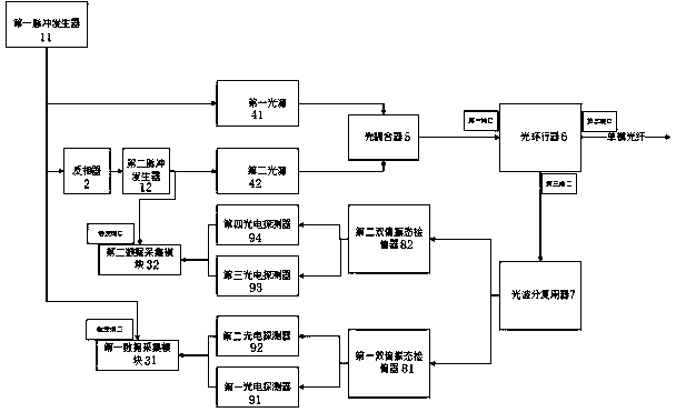
[0021] Such as figure 1 As shown, the present invention provides a polarization state fiber optic vibration sensing system based on time division multiplexing. The first pulse generator 11 transmits pulse signals to the first light source 41 , the first data acquisition module 31 and the inverter 2 . The first light source 41 converts the pulse signal into pulse light and sends it to the optical coupler 5 , and the first data collection module 31 acts after receiving the pulse signal to start data collection. The first pulse generator 11 is used to send a pulse with a pulse width W to the first light source 41 , the inverter 2 and the first data acquisition module 31 , and the duty ratio of the pulse is less than 0.5.

[0022] The output port of the inverter 2 is connected to the trigger port of the second pulse generator 12, and the output port of the second pulse generator 12 is connected to the input port of the second light source 42, and the second light source 42 convert...

Embodiment 2

[0033] In this embodiment, both the first light source 41 and the second light source 42 are narrow-band light sources, the sensing fiber is a single-mode fiber, the specific signal is G.652D, the wavelength λ1 of the emitted light of the first narrow-band light source and the wavelength of the emitted light of the second narrow-band light source λ2 are 1310nm and 1550nm respectively. The central wavelengths of the two demultiplexing ports of the optical wavelength division multiplexer 7 are 1310nm and 1550nm respectively, and its 1310 demultiplexing port is connected with the input port of the first dual polarization state analyzer 81, and the 1550 demultiplexing port is connected with the second dual polarization state detecting device. The input port of polarizer 82 is connected.

[0034] The end of the sensing fiber away from the second port of the optical circulator 6 is cut off by a bevel, which is used to reduce the reflection of light on the section at the end of the f...


PUM


Abstract

The invention relates to an optical fiber sensing system, and particularly relates to a time division multiplexing-based polarization state optical fiber vibration sensing system. The system comprisesa first pulse generator. The output end of the first pulse generator is connected with a first light source, a phase inverter and a first data acquisition module. The phase inverter is connected witha second pulse generator. The second pulse generator is connected with a second light source. The first light source and the second light source are connected with a first port of an optical circulator through an optical coupler. The optical circulator is connected with a sensing optical fiber. The optical circulator transmits the scattered light to an optical wavelength division multiplexer through a third port. The optical wavelength division multiplexer is connected with a photoelectric detector through a polarization analyzer. The photoelectric detector is connected with the first data acquisition module. According to the invention, the higher vibration sensing sensitivity is achieved, and meanwhile the higher system stability is achieved.

Description

technical field [0001] The invention relates to an optical fiber sensing system, more specifically, to a polarization state optical fiber vibration sensing system based on time division multiplexing. Background technique [0002] The optical fiber vibration sensing system based on POTDR sensing technology is a new type of sensor that achieves the purpose of distributed optical fiber sensing by detecting the polarization state change in the optical fiber. Because it can detect weak stress changes, it has a wide application prospect. [0003] With the implementation of the urban high-voltage cable laying project from the air to the ground, the current urban power transmission lines basically use the form of underground tunnels to transport electricity. It is more and more important to monitor the safety and health of urban power transmission network, find faults in time, and ensure the normal operation of society. However, the on-site environment of the cable tunnel is very h...

Claims


Application Information

Patent Timeline
Patent Type & Authority Applications(China)
IPC IPC(8): G01H9/00G01D5/30
CPCG01D5/30G01H9/004
Inventor 曾强李锡熙李伟德龙葵尚晋蓝海森李纳新陈少峰刘嘉威李仕良
Owner GUANGDONG POWER GRID CO LTD DONGGUAN POWER SUPPLY BUREAU
Why Eureka
Try Eureka