Power-on and power-off tester

A technology of power-off testing and relay modules, applied in the direction of testing dielectric strength, instruments, measuring electricity, etc., can solve problems such as circuit hidden dangers, and achieve good results

Inactive Publication Date: 2018-09-18
SHENZHEN C&D ELECTRONICS
View PDF5 Cites 0 Cited by
  • Summary
  • Abstract
  • Description
  • Claims
  • Application Information

AI Technical Summary

Problems solved by technology

[0003] The technical purpose of the present invention is to overcome the technical problem that the power-on and power-off tester of the current electronic product has a fixed switching time and cannot fully test the hidden dangers of the circuit in the prior art; , a power-on and power-off tester that provides a comprehensive test of the device under test in terms of power-on and power-off

Method used


Image

  • Power-on and power-off tester
  • Power-on and power-off tester
  • Power-on and power-off tester

Examples


Embodiment Construction

[0024] Embodiments of the present invention are described in detail below, examples of which are shown in the drawings, wherein the same or similar reference numerals designate the same or similar elements or elements having the same or similar functions throughout. The embodiments described below by referring to the figures are exemplary and are intended to explain the present invention and should not be construed as limiting the present invention.

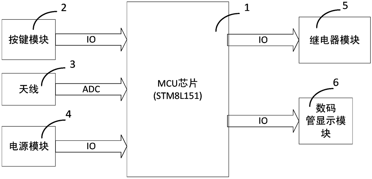
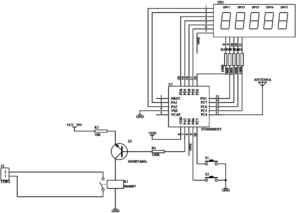
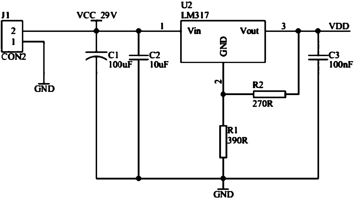
[0025] In one embodiment of the present invention, as Figure 1-4 As shown, a power-on and power-off tester includes an MCU chip 1, a button module 2, an antenna 3, a power module 4, a relay module 5, and a digital tube display module 6; the input terminals of the MCU chip 1 are respectively connected to the antenna 3 and the button Module 2, the output terminal of MCU chip 1 is respectively connected to the input terminal of relay module 5 and the input terminal of digital tube display module 6, the power supply terminal of MCU ...


PUM


Abstract

The invention provides a power-on and power-off tester, which comprises an MCU chip, a button module, an antenna, a power module, a relay module and a nixie tube display module, wherein an input end of the MCU chip is connected with the antenna and the button module respectively, an output end of the MCU chip is connected with an input end of the relay module and an input end of the nixie tube display module, a power supply end of the MCU chip is connected with the power module, and an output end of the relay module is connected with a power supply end of tested equipment. The power-on and power-off tester controls the random power-on and power-off conditions of the tested equipment by means of the antenna, the MCU chip and the relay module, and controls the timing power-on and power-off conditions of the tested equipment by means of the button module, the MCU chip and the relay module, thereby being capable of providing the tested equipment with a comprehensive test environment for power-on and power-off.

Description

technical field [0001] The invention relates to the technical field of testers, more specifically, to a power-on and power-off tester for electronic products. Background technique [0002] In the prior art, since many electronic products under test contain capacitors in their internal circuits, and the sizes of the capacitors are different, the discharge time of some of the capacitors after the product is powered off is uncertain, and the delayed discharge of the capacitors will cover up the timing of power on and off. Defects on some circuits cannot find hidden dangers in the circuit. The current power-on and power-off testers of electronic products have technical defects that the product cannot detect hidden dangers in time due to the uncertain capacitor discharge time, which has become a technical problem urgently to be solved by those skilled in the art. Contents of the invention [0003] The technical purpose of the present invention is to overcome the technical prob...

Claims


Application Information

Patent Timeline
IPC IPC(8): G01R31/00G01R31/12
CPCG01R31/00G01R31/1227
Inventor 雷军平
Owner SHENZHEN C&D ELECTRONICS
Why Eureka
Try Eureka