Automatic comb plate device of novel lead storage battery
A lead-acid battery and comb technology, which is applied in the field of automatic comb devices for new-type lead-acid batteries, can solve problems such as low production efficiency, easy falling off of active materials, and large internal resistance, so as to improve quality and production efficiency, reduce labor intensity, The effect that is conducive to popularization and use
- Summary
- Abstract
- Description
- Claims
- Application Information
AI Technical Summary
Problems solved by technology
Method used
Image

Examples
specific Embodiment approach 1
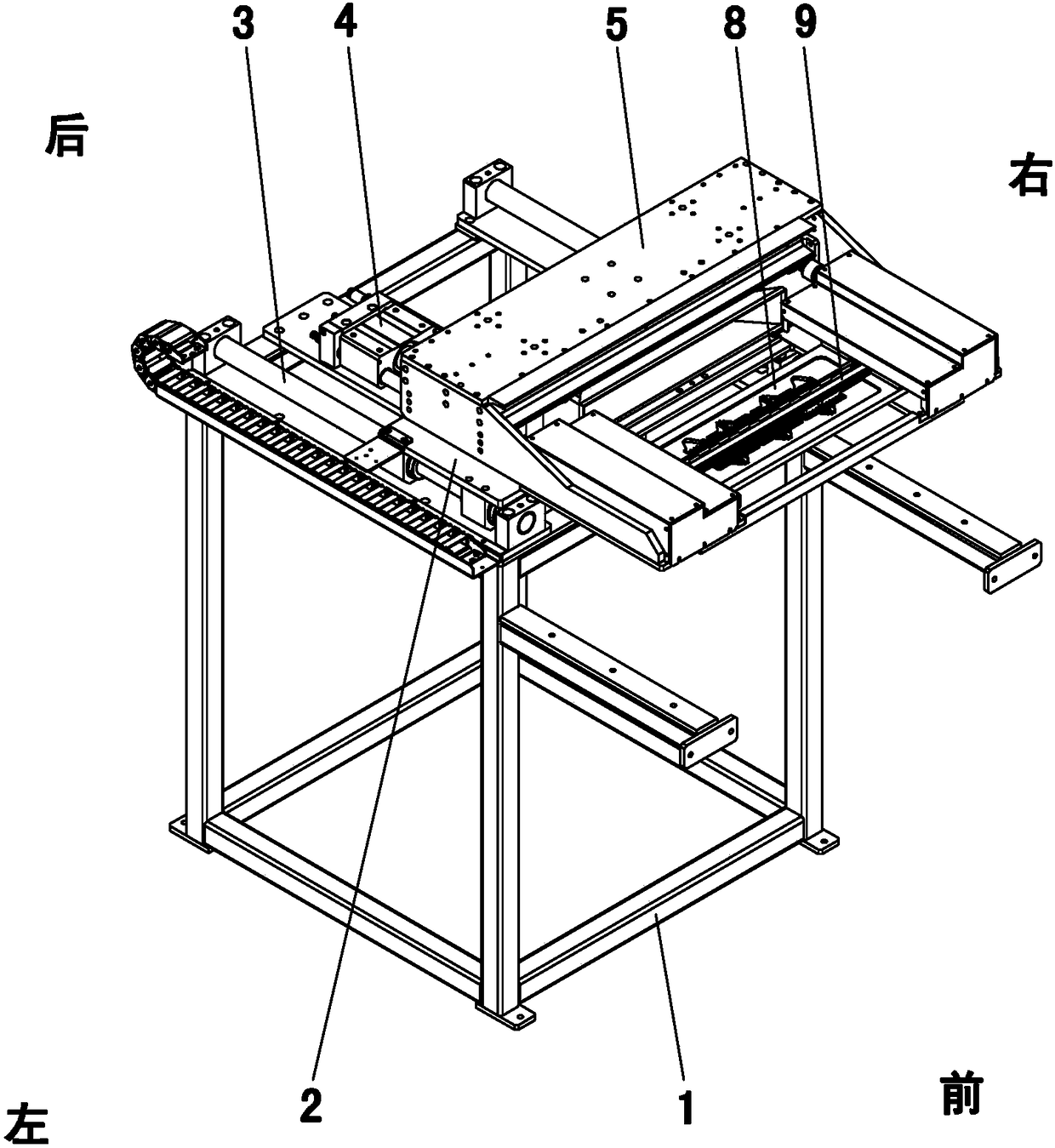
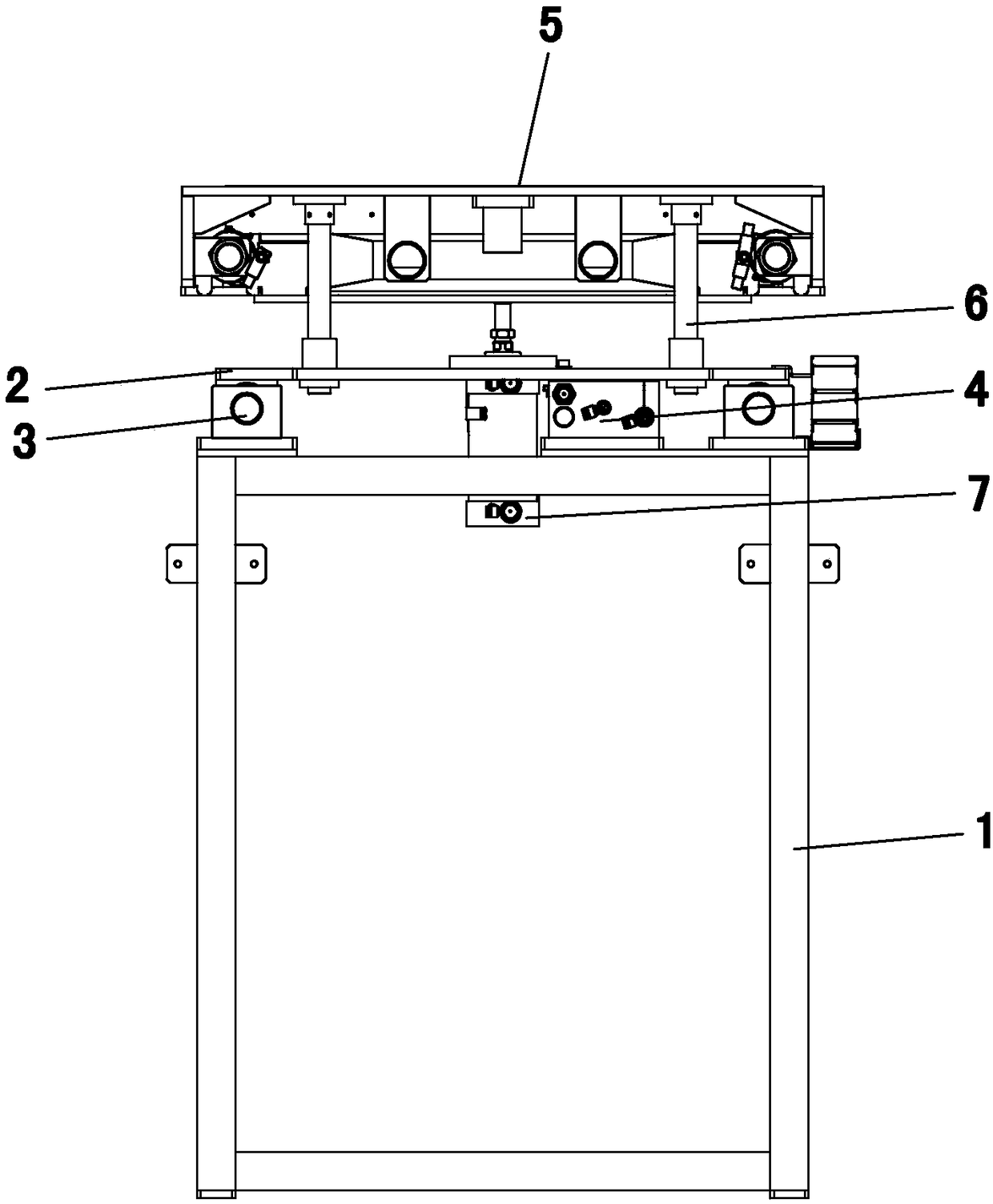
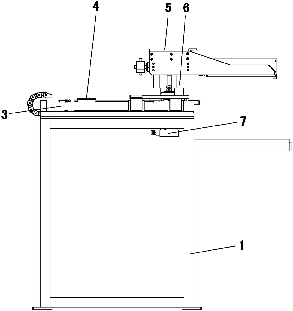
[0016] Specific implementation mode one: as Figure 1 to Figure 7 As shown, the present invention discloses a novel lead-acid battery automatic combing device, comprising a frame 1, a mobile platform 2, a translation cylinder 4, a lifting cylinder 7 and a comb mechanism, and the left and right sides of the upper surface of the frame 1 are arranged side by side. Two horizontal guide shafts 3 are fixed, and the mobile platform 2 is connected with the two horizontal guide shafts 3 through linear bearings and can be slid back and forth. The translation cylinder 4 is used to control the mobile platform 2, and the translation cylinder 4. The housing is fixedly connected to the frame 1, and the outer end of the piston rod of the translation cylinder 4 is fixedly connected to the mobile platform 2. The comb mechanism includes a comb box 5, a comb stopper 9 and two comb plates 8. The comb box 5 is arranged above the mobile platform 2, and the upper surface of the mobile platform 2 is r...
specific Embodiment approach 2
[0017] Specific implementation mode two: as Figure 5 As shown, this embodiment is a further description of Embodiment 1. The comb box 5 includes a bottom plate 5-1 and two side risers 5-2, and the two side risers 5-2 They are fixed side by side on the left and right sides of the base plate 5-1, and the comb stop middle partition 9 and the two comb plates 8 are arranged in the middle position of the front end of the upper surface of the base plate 5-1.
specific Embodiment approach 3
[0018] Specific implementation mode three: as Figure 5 , 6 As shown, this embodiment is a further description of the second specific embodiment. Two slide rails are arranged side by side on the left and right sides of the upper surface of the bottom plate 5-1, and two sliding rails are installed on each slide rail. a slider 11, the comb stop middle partition 9 is fixed at the middle position between the two slide rails on the upper surface of the bottom plate 5-1, and the two comb plates 8 are located at the front and rear sides of the comb stop middle partition 9, The left and right ends of the two comb plates 8 are respectively affixed to the corresponding sliders 11, and the middle positions of the inner surfaces of the two side vertical plates 5-2 are respectively rotated and installed with a gear 12, and each of the gears 12 Correspondingly, there are two transmission rods 13, and the two transmission rods 13 are respectively provided with teeth along their length direc...
PUM
 Abstract
Description
Claims
Application Information