
Method for separating and recycling naphthalene residual oil

A technology for separation and recovery of residual oil, applied in crystallization purification/separation, chemical instruments and methods, purification/separation of hydrocarbons, etc., can solve problems such as increasing the cost of tail gas desulfurization, easy to pollute the environment, and increasing the sulfur concentration of carbon black tail gas , to achieve the effective utilization of resources and increase the content of naphthalene

Active Publication Date: 2018-09-21
山西豪仑科化工有限公司
View PDF4 Cites 0 Cited by
  • Summary
  • Abstract
  • Description
  • Claims
  • Application Information

AI Technical Summary

Problems solved by technology

[0002] Under normal circumstances, the raw material industrial naphthalene with a naphthalene content of about 95.9% is further crystallized by a crystallizer to increase the naphthalene content to 99.3%, and the remaining naphthalene residue (containing about 50% naphthalene and 30% benzothiophene) is mixed into the carbon black oil Production of carbon black, although this utilization method solves the outlet problem of the by-product naphthalene residual oil, it also brings disadvantages: 1) The benzothiophene in the naphthalene residual oil contains 23.8% sulfur, and the sulfur concentration in the carbon black tail gas increases, which is easy to It pollutes the environment and increases the cost of tail gas desulfurization; 2) 50% of naphthalene and 30% of benzothiophene in naphthalene residual oil are burned in vain, resulting in a great waste of resources

Method used


Image

  • Method for separating and recycling naphthalene residual oil

Examples


Embodiment 1

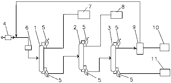
[0023] Such as figure 1 as shown,

[0024] A method for separating and recovering naphthalene residual oil, comprising the following steps carried out in sequence:

[0025] Feed: adjust the pressure of raw naphthalene residual oil at 15kPa through the feed pump, and the mass flow rate is 859kg / hr. After mixing with the crystallization mother liquor through a mixer, send it to the light removal tower. The temperature of the mixed liquor is 47.9°C;

[0026] Light removal: keep the temperature of the light removal tower at 130-170°C, and separate the light components in the raw naphthalene residual oil. After separation, the light gas phase components at the top of the tower are condensed and sent to the condensate tank, and the liquid in the condensation tank is refluxed A part of the pump is sent to the top of the tower as reflux, and the other part is sent to the light component storage tank as a by-product; the material discharged from the bottom of the light removal tower i...

Embodiment 2

[0040] A method for separating and recovering naphthalene residual oil, comprising the following steps carried out in sequence:

[0041] Feed: Raw naphthalene residual oil passes through the feed pump, mixes with the crystallization mother liquor through a mixer, and then sends it to the light removal tower. The temperature of the mixed liquor is 60°C;

[0042] Light removal: keep the temperature of the light removal tower at 130-170°C, and separate the light components in the raw naphthalene residual oil. After separation, the light gas phase components at the top of the tower are condensed and sent to the condensate tank, and the liquid in the condensation tank is refluxed A part of the pump is sent to the top of the tower as reflux, and the other part is sent to the light component storage tank as a by-product; the material discharged from the bottom of the light removal tower is sent to the naphthalene removal tower;

[0043] Naphthalene removal: Keep the temperature of th...

Embodiment 3

[0052] A method for separating and recovering naphthalene residual oil, comprising the following steps carried out in sequence:

[0053] Feed: Raw naphthalene residual oil passes through the feed pump, mixes with the crystallization mother liquor through a mixer, and then sends it to the light removal tower. The temperature of the mixed liquor is 40°C;

[0054] Light removal: keep the temperature of the light removal tower at 130-170°C, and separate the light components in the raw naphthalene residual oil. After separation, the light gas phase components at the top of the tower are condensed and sent to the condensate tank, and the liquid in the condensation tank is refluxed A part of the pump is sent to the top of the tower as reflux, and the other part is sent to the light component storage tank as a by-product; the material discharged from the bottom of the light removal tower is sent to the naphthalene removal tower;

[0055] Naphthalene removal: Keep the temperature of th...


PUM


Abstract

The invention discloses a method for separating and recycling naphthalene residual oil. The method sequentially includes steps of feeding a raw material which is the naphthalene residual oil; removinglight components, to be more specific, separating the light components in the naphthalene residual oil and delivering tower bottom discharged materials to naphthalene removal towers; removing naphthalene, to be more specific, condensing tower top gas phase by the aid of condensers, then delivering a part to tower tops to be used as reflux, delivering another part to naphthalene refining sectionsand delivering tower bottom discharged materials to benzothiophene towers; removing benzothiophene, to be more specific, condensing tower top gas phase by the aid of condensers, then feeding condensedfluid into condensed fluid tanks, delivering a part to tower tops to be used as reflux, delivering another part into static crystallizers, delivering tower bottom discharged materials to byproduct storage tanks and returning mother liquor to light component removal towers by means of circulation. The method has the advantages that benzothiophene products in the naphthalene residual oil are extracted, accordingly, the naphthalene content can be increased, refined naphthalene can be processed in crystallizers, and resources can be optimally effectively utilized; naphthalene residual oil recycling is coupled with naphthalene refining devices, accordingly, naphthalene consumption can be reduced and can reach 1.04 tons industrial naphthalene / ton refined naphthalene, and the benzothiophene yield can reach 70% at least.

Description

technical field [0001] The invention discloses a method for separating and recovering naphthalene residual oil, which belongs to the technical field of coal tar washing oil processing. Background technique [0002] Under normal circumstances, the raw material industrial naphthalene with a naphthalene content of about 95.9% is further crystallized by a crystallizer to increase the naphthalene content to 99.3%, and the remaining naphthalene residue (containing about 50% naphthalene and 30% benzothiophene) is mixed into the carbon black oil Production of carbon black, although this utilization method solves the outlet problem of the by-product naphthalene residual oil, it also brings disadvantages: 1) The benzothiophene in the naphthalene residual oil contains 23.8% sulfur, and the sulfur concentration in the carbon black tail gas increases, which is easy to It pollutes the environment and increases the cost of tail gas desulfurization; 2) 50% of naphthalene and 30% of benzothi...

Claims


Application Information

Patent Timeline
IPC IPC(8): C07C7/00C07C7/14C07C15/24C07D333/54
CPCC07C7/005C07C7/14C07D333/54C07C15/24
Inventor 李斌革李康杰张少军
Owner 山西豪仑科化工有限公司
Learn More