

Circular hollow interlayer splicing column and construction method thereof
A splicing column and hollow technology, applied in the directions of columns, pillars, piers, etc., can solve the problems of complex design and construction of connecting components, insufficient joint stiffness, insufficient working surface, etc., and achieve high assembly efficiency, enhanced shear bearing capacity, and construction. low difficulty effect
- Summary
- Abstract
- Description
- Claims
- Application Information
AI Technical Summary
Problems solved by technology
Method used
Image

Examples
Embodiment 1
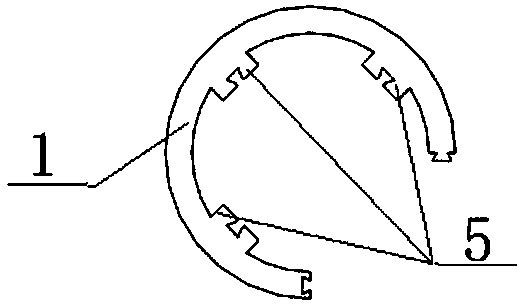
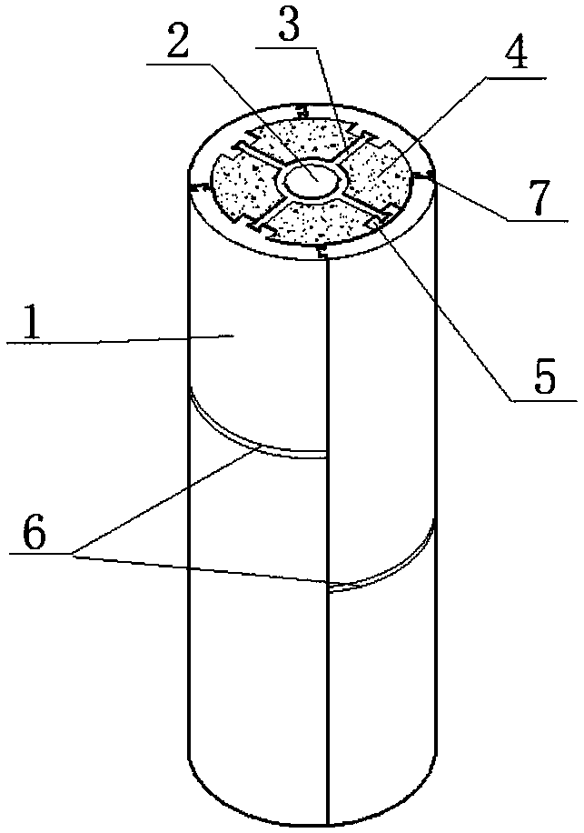
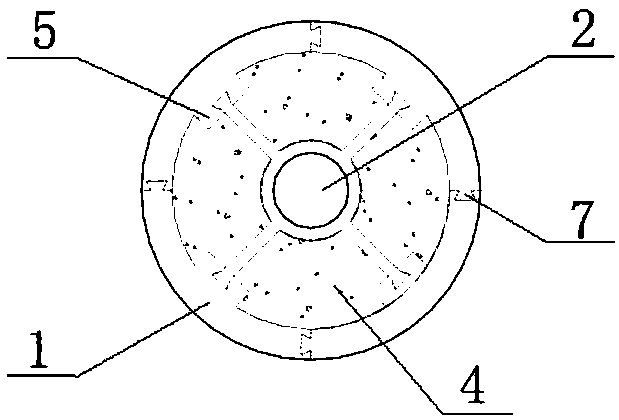
[0040] Such as figure 1 and figure 2 As shown, the circular hollow interlayer splicing column of the present invention includes an outer cylindrical column 1 formed by vertical insertion and fixing of at least two skeleton units, and an inner cylindrical column member fixed in the outer cylindrical column 1, The inner wall of the outer cylindrical pipe string 1 is welded with at least one anti-slip groove 5; the inner cylindrical pipe string member includes an inner cylindrical pipe string 2 arranged concentrically with the outer cylindrical pipe string 1, and a number of vertically welded pipe strings along the outer wall of the inner cylindrical pipe string 2. Steel partitions 3 of equal length, the steel partitions 3 are spaced from each other and the ends are provided with anti-off heads 8 matching with anti-off grooves 5; the inner cylindrical column 2 is inserted through the anti-off heads 8 of the steel partitions The anti-detachment groove 5 connected to the outer cy...
Embodiment 2
[0046] The cross-sections of the skeleton units in the present invention can be varied, and the outer cylindrical pipe string 1 can also be spliced by various skeleton units.
[0047] For example, as shown in Fig. 3(a), the cross-section of the skeleton unit is 90° fan-shaped. Such as figure 1 and figure 2 As shown, the outer cylindrical pipe string 1 is spliced by four skeleton units whose sections are 90° fan-shaped.
[0048] As shown in Fig. 3(b), the cross-section of the skeleton unit is 180° fan-shaped. Such as Figure 6 and Figure 7 As shown, the outer cylindrical pipe string 1 is spliced by two skeleton units whose sections are 180° fan-shaped.
[0049] As shown in Fig. 3(c), the cross-section of the skeleton unit is 270° fan-shaped. Such as Figure 8 and Figure 9 As shown, the outer cylindrical pipe string 1 is spliced by a skeleton unit with a sector-shaped cross section of 90° and a skeleton unit with a sector-shaped cross-section of 270°.
Embodiment 3
[0051] In the frame unit of the present invention, the vertical height dimensions of the left and right sides are inconsistent.
[0052] For example, if figure 1 There are multiple skeleton units in the perspective view shown, among which, among the skeleton units in the lower layer, the vertical height dimensions of the leftmost and rightmost skeleton units are smaller than the vertical height dimensions of the middle skeleton units; similarly, the upper layer Among the skeletal units of , the vertical height dimensions of the leftmost and rightmost skeletal units are larger than the vertical height dimensions of the middle side skeletal units. In this way, the skeleton units of the lower layer and the upper layer cooperate to form a complete outer cylindrical pipe string 1 .
[0053] Such as Figure 6 There are multiple skeleton units in the perspective view shown, among them, in the skeleton unit of the lower layer, the vertical height dimension of the left side is larger...
PUM
 Abstract
Description
Claims
Application Information