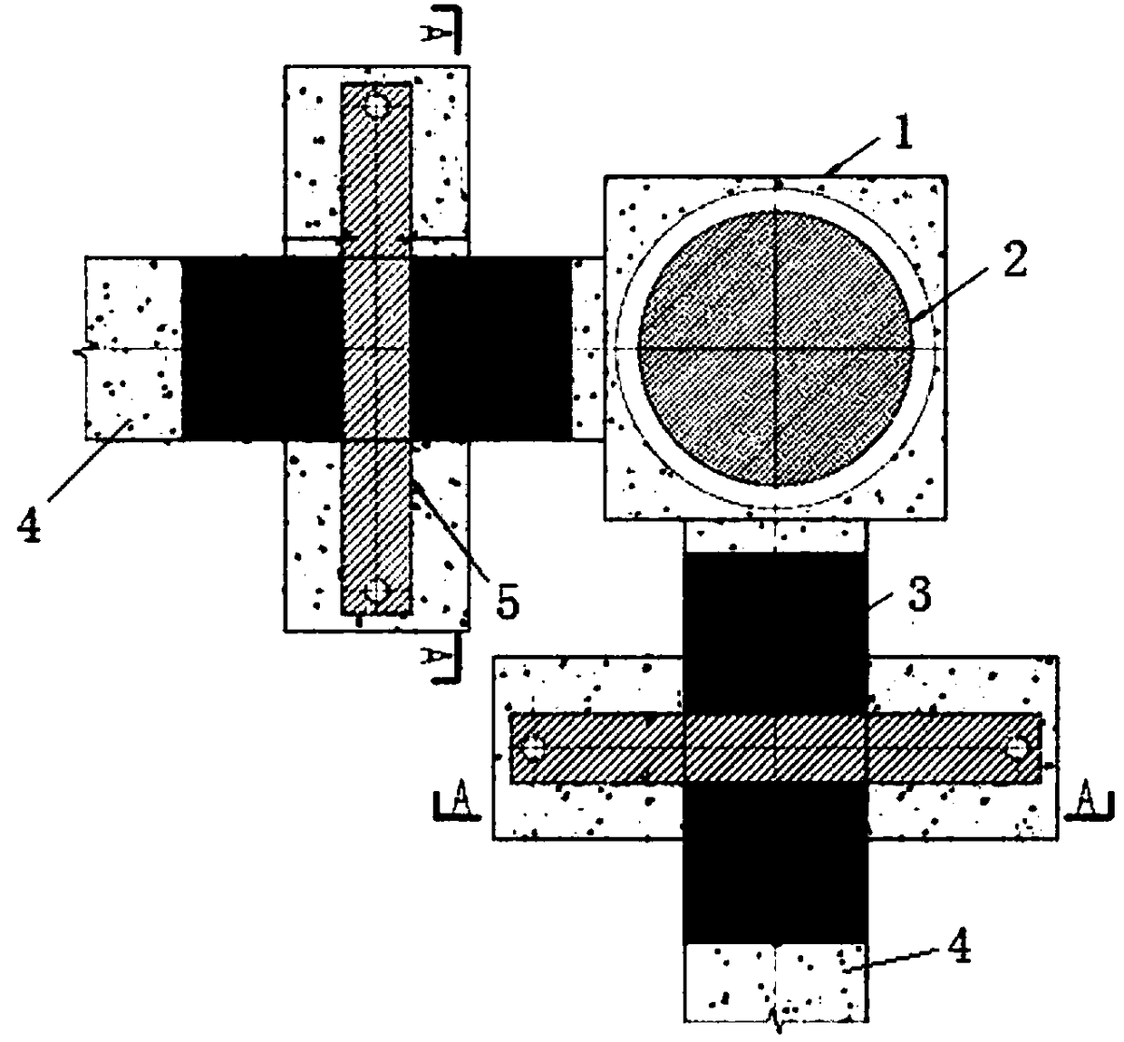
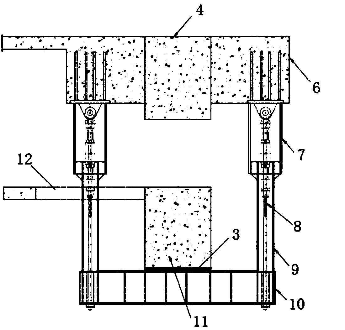
Shock insulation layer prestress tensile device

A seismic isolation layer, prestressing technology, applied in the direction of earthquake resistance, structural elements, building components, etc., can solve the problems of increasing the tensile force with additional stiffness, the requirement that the tensile device should not be used for a large tensile force level, and the difficulty of convergence.

Pending Publication Date: 2018-09-21
BEIJING INST OF ARCHITECTURAL DESIGN
View PDF9 Cites 2 Cited by
  • Summary
  • Abstract
  • Description
  • Claims
  • Application Information

AI Technical Summary

Problems solved by technology

[0005] The survey found that the existing tensile devices are not suitable for the requirements of higher tensile levels
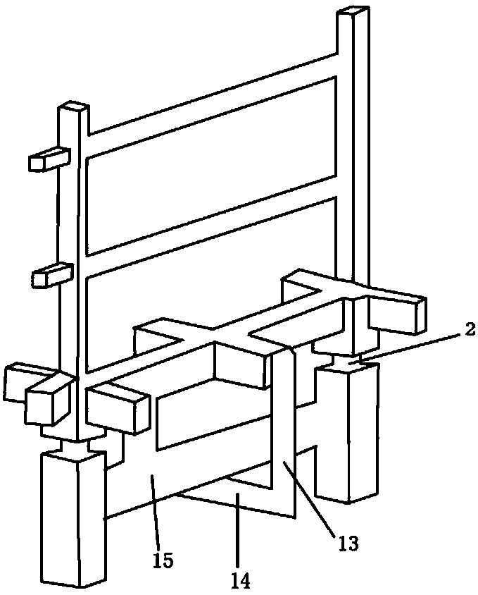
For example, the tensile device type 1 proposed by some scholars (see image 3 ), image 3 Middle 2 is the seismic isolation support, 13 is the tie rod, 14 is the cross bar, and 15 is the special beam for seismic isolation. This device will add a larger tensile stiffness, and the additional stiffness will be significantly greater than the tensile stiffness of the rubber bearing. It is basically equivalent to the compressive stiffness. For high-intensity areas with large overturning moments, excessive additional stiffness will significantly increase the tensile force. When the load is insufficient, the section of the steel member will be increased, and the final convergence will be very difficult.

Method used


Image

  • Shock insulation layer prestress tensile device
  • Shock insulation layer prestress tensile device
  • Shock insulation layer prestress tensile device

Examples


Embodiment Construction

[0033] The technical solution of the present invention will be further described by specific embodiments below.

[0034] Hereinafter, the present invention will be described more comprehensively with reference to the accompanying drawings, in which exemplary embodiments of the present invention are shown. However, the present invention can be embodied in many different forms, and should not be understood as being limited to the exemplary embodiments described herein. Rather, these embodiments are provided so that the present invention will be comprehensive and complete, and will fully convey the scope of the present invention to those of ordinary skill in the art.

[0035] For ease of description, spatially relative terms such as "upper", "lower", "left" and "right" may be used here to describe the relationship between one element or feature shown in the figure relative to another element or feature . It should be understood that, in addition to the orientations shown in the figu...


PUM


Abstract

The invention provides a shock insulation layer prestress tensile device. The device comprises inhaul cables and a steel box girder, one end of each inhaul cable is connected with a top beam of a shock insulation layer through a connecting beam, and the other end of each inhaul cable penetrates through a bottom beam of the shock insulation layer and is connected with the steel box girder; a devicefor reducing friction force is arranged on the contact surface of the bottom beam of the shock insulation layer and the steel box girder. The tensile device has the advantages that the additional tensile rigidity is small, the total tension of the position of a support can be effectively optimized, the tension level of an upper structure and a lower structure connected with the support is reduced, the construction cost is reduced, quantitative analysis of the tensile device can be achieved, a basis is provided for the design of the tensile device, and a tensile device prestress design methodis deduced.

Description

Technical field [0001] The invention relates to the field of bridges, and more specifically to a prestressed tensile device for a seismic isolation layer. Background technique [0002] my country is a country with frequent earthquakes. In recent years, there have been major earthquakes in Wenchuan and Ya'an. The earthquakes have caused a large number of casualties and huge property losses. Even though some buildings have reached the design goal of earthquake-resistant design, The destruction of the infill wall and the decoration secondary structure caused casualties. Therefore, it has been repeatedly mentioned at the government level that it is recommended to promote seismic isolation technology to improve the seismic performance of the structure to ensure the safety of personnel. In some areas with high design intensity, the use of seismic isolation technology for important buildings has greatly promoted my country's seismic isolation. Technology development. [0003] Since common...

Claims


Application Information

Patent Timeline
Patent Type & Authority Applications(China)
IPC IPC(8): E04C5/08E04B1/98E04H9/02E01D19/00E01D101/32
CPCE01D19/00E04C5/08E04H9/021E01D2101/32
Inventor 卜龙瑰苗启松朱忠义閤东东邢珏蕙黄章云
Owner BEIJING INST OF ARCHITECTURAL DESIGN
Why Eureka
Try Eureka