Method for detecting mechanical response of mechanical components by using organic mechanoluminescent material

一种机械部件、致发光的技术,应用在通过测量材料受应力时其光学性质的变化力的计量、采用光学装置、使用施加稳定的张力/压力测试材料强度等方向,能够解决非可再生、环氧树脂流动性差、无机材料与金属相容性差等问题,达到准确定性及定量分析、适用范围广、方法简单的效果

Inactive Publication Date: 2018-10-19
TIANJIN UNIV +1
View PDF7 Cites 14 Cited by
  • Summary
  • Abstract
  • Description
  • Claims
  • Application Information

AI Technical Summary

Problems solved by technology

[0004] Due to the poor compatibility between inorganic materials and metals, it is usually necessary to use an additional organic epoxy resin as an adhesive, and the fluidity of epoxy resin is poor, which makes it difficult to use on a large scale
At the same time, inorganic materials are also biologically toxic and non-renewable, which limits their wide application to a certain extent.

Method used


Image

  • Method for detecting mechanical response of mechanical components by using organic mechanoluminescent material
  • Method for detecting mechanical response of mechanical components by using organic mechanoluminescent material
  • Method for detecting mechanical response of mechanical components by using organic mechanoluminescent material

Examples


Embodiment 1

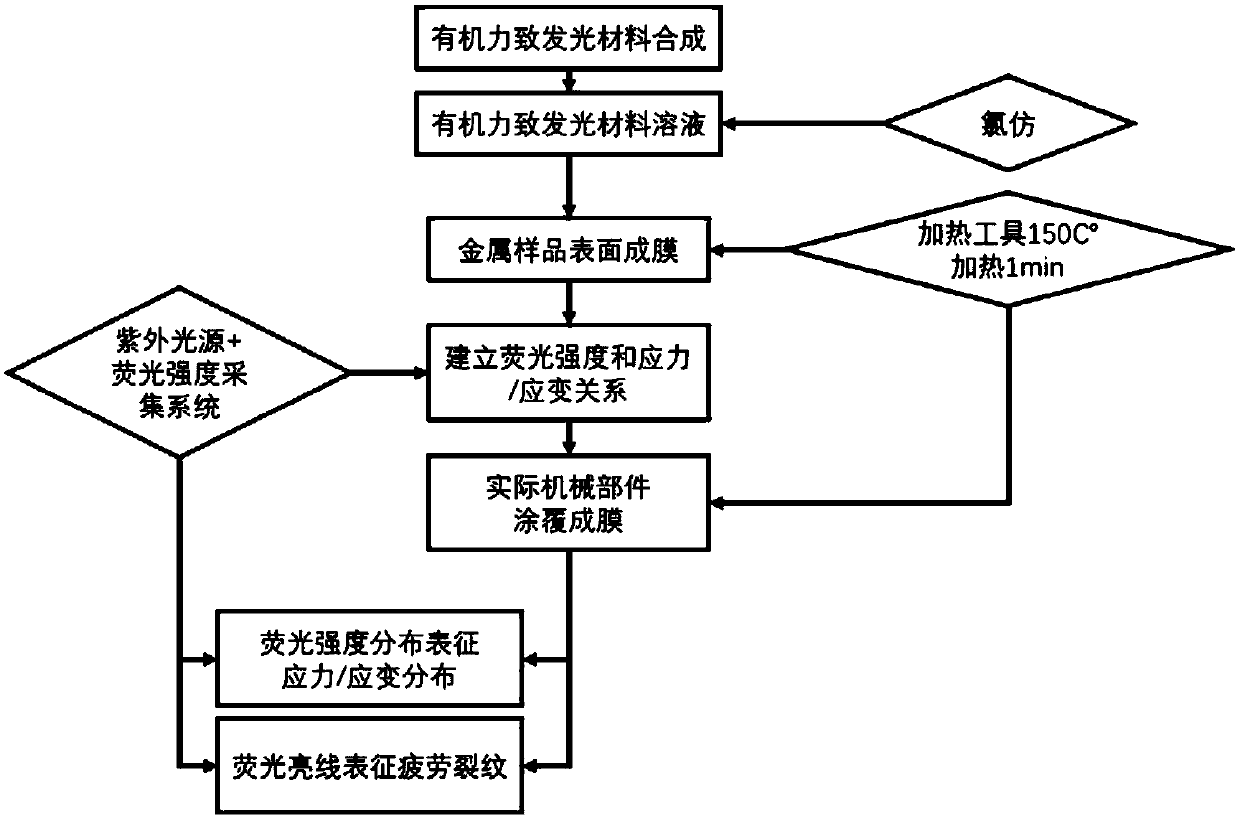
[0048] Example 1: Dissolve TPE-4N in chloroform to prepare a TPE-4N solution with a concentration of 0.01g / mL, apply the solution on the metal surface with a brush, and heat at 80°C for 20 minutes with a heat gun to form a film.

Embodiment 2

[0049] Example 2: TPE-4N was dissolved in chloroform to prepare a TPE-4N solution with a concentration of 0.3g / mL, and the solution was applied to the metal surface with a brush, and heated at 150°C for 1 minute with a heat gun to form a film.

Embodiment 3

[0050] Example 3: TPE-4N was dissolved in chloroform to prepare a TPE-4N solution with a concentration of 1 g / mL, and the solution was applied to the metal surface with a brush, and heated at 300° C. for 30 seconds with a heat gun to form a film. Heating tools can use heat guns, ovens, heating mantles, etc. with consistent results.

[0051] The results of coating the TPE-4N film on the metal surface with any of the solutions prepared above in Examples 1, 2, and 3 are consistent; the TPE-4N solution is stored in a light-shielding low temperature place.

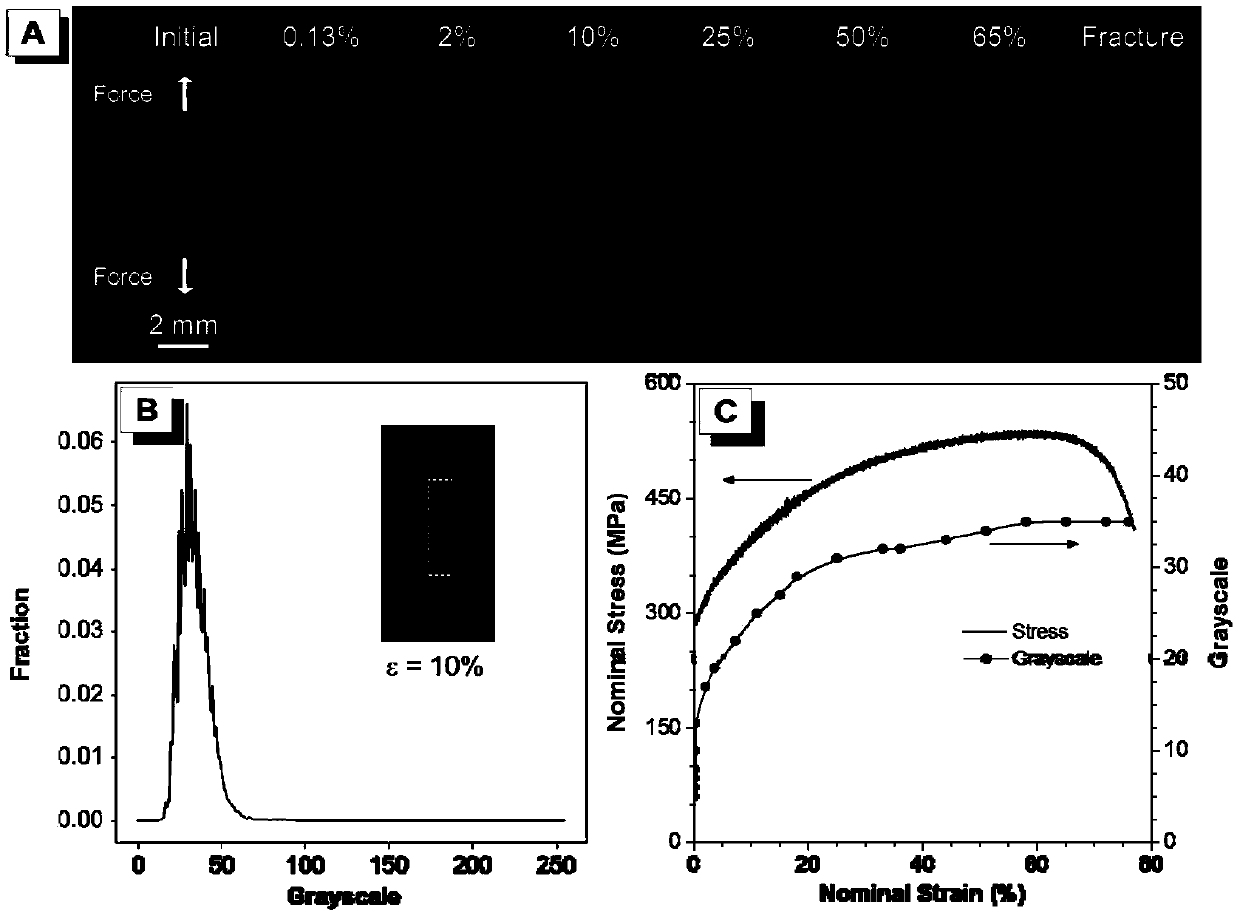
[0052] (4) Fluorescence intensity calibration. Such as figure 2 As shown, a uniaxial tensile test was carried out on a 316L stainless steel metal sample coated with TPE-4N, and an ultraviolet light source was used as an excitation light source to irradiate the coating on the sample. In different stress / strain response stages, a CCD camera system was used to obtain And record the fluorescent photos on the sample ( figure 2 ...


PUM

PropertyMeasurementUnit
composition ratioaaaaaaaaaa

Abstract

The invention discloses a method for detecting mechanical response of mechanical components by using an organic mechanoluminescent material. The method includes the following steps: selecting an organic mechanoluminescent material, preparing an organic mechanoluminescent material solution; uniformly coating the surface of a metal sample with the organic mechanoluminescent material solution, and heating the metal sample to form a film; calibrating the fluorescence intensity, using ultraviolet light as an excitation light source to illuminate the organic mechanoluminescent material film on the surface of a gauge section of the metal tensile sample, collecting fluorescence intensity data of the organic mechanoluminescent material film by using a detection device, and establishing correlationdata between the fluorescence intensity and stress / strain intensity; actually detecting the mechanical components, comparing the detection data with fluorescence intensity sample data and analyzing the detection data, and determining magnitude and distribution of stress / strain received by the components based on the fluorescence intensity; monitoring whether a fatigue crack occurs at a to-be-detected position by observing a fluorescent bright line generated by the organic mechanoluminescent material at the crack; and predicting the direction of crack propagation by using the fluorescence intensity distribution near the crack tip.

Description

technical field [0001] The invention relates to a method for dynamically and visually detecting the full-field stress / strain distribution and fatigue crack propagation path of a mechanical component by using an organic luminescent material with a force-induced response property. Background technique [0002] Stress / strain distribution is the basis for the design and safety assessment of mechanical components. With the development of industry, large and complex components are widely used in aerospace, high-speed rail and automobiles. Therefore, it is necessary to realize the detection of a wide range of stress / strain and crack defects, which is of great significance to ensure the safety of personnel and equipment. Especially for complex structures, the fatigue failure caused by local stress concentration has large errors between theoretical calculations and actual results, and cannot be completely and accurately predicted. In traditional stress / strain distribution measuremen...

Claims


Application Information

Patent Timeline
Patent Type & Authority Applications(China)
IPC IPC(8): G01L1/24G01B11/16G01N21/64
CPCG01B11/16G01L1/24G01N21/64G01N2021/646G01N21/6456G01L1/247G01N2203/0064G01N2203/0075G01N2203/0641G01N3/068G01N3/08G01N2203/0017G01N2203/0066G01N2203/0073
Inventor 张喆唐本忠陈旭丘子杰赵伟军
Owner TIANJIN UNIV
Why Eureka
Try Eureka