Earthquake imaging method

An imaging method and imaging technology, applied in the field of exploration, can solve the problems of fuzzification of imaging results, difficulty in satisfying lithology interpretation, low amplitude fidelity of wave field bandwidth migration imaging results and low imaging resolution, etc. The effect of precise imaging results

Inactive Publication Date: 2018-09-21
NORTHEAST GASOLINEEUM UNIV
View PDF3 Cites 3 Cited by
  • Summary
  • Abstract
  • Description
  • Claims
  • Application Information

AI Technical Summary

Problems solved by technology

For complex exploration targets such as lithologic reservoirs, complex reservoirs, and hidden reservoirs, conventional structural imaging has been unable to meet the needs of oil and gas industrial production. The above-mentioned seismic migration imaging technology is facing the following practical problems: sparse receiving points Factors such as sampling, narrow acquisition aperture, and limited wavefield bandwidth often lead to low amplitude fidelity and imaging resolution of migration imaging results, which are difficult to meet the needs of lithology interpretation
In essence, migration imaging is the result of the underground reflection coefficient filtered by the Hessian operator, but the Hessian operator will blur the imaging results

Method used


Image

  • Earthquake imaging method
  • Earthquake imaging method
  • Earthquake imaging method

Examples


specific Embodiment

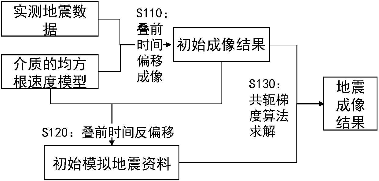
[0036] Such as figure 1 A flow chart of the migration imaging method provided by the embodiment of the present invention is shown. See figure 1 , the migration imaging method includes:

[0037] Step S110: performing pre-stack time migration imaging based on the measured seismic data and the root-mean-square velocity model of the medium to obtain an initial imaging result.

[0038] In the embodiment of the present invention, the pre-stack time migration imaging formula may be the Kirchhoff pre-stack time migration formula, specifically:

[0039] ,

[0040] in, τ is the two-way travel time (imaging time) perpendicular to the ground corresponding to the imaging point, x is the ground coordinate corresponding to the underground scattering point (imaging point), m is the ground coordinate corresponding to the center point, half offset The gather at the imaging point (x, τ ) at the prestack time imaging value.

[0041] In the embodiment of the present invention, before...


PUM


Abstract

The present invention provides an earthquake imaging method, and relates to the technical field of exploration. The method comprises the steps of: based on actually measured earthquake data and a dielectric root-mean-square speed model, performing pre-stack time migration imaging to obtain an initial imaging result; performing pre-stack time demigration based on the initial imaging result and thedielectric root-mean-square speed model, and obtaining initial simulation earthquake data; employing a conjugate gradient algorithm to perform solution based on the initial imaging result and the initial simulation earthquake data to obtain an imaging result corresponding to the simulation earthquake data when the errors of the simulation earthquake data and the actually measured earthquake data is smaller than or equal to a preset error as a final earthquake imaging result. The earthquake imaging method can better eliminate the fuzzification influence of an Hessian operator on the imaging result when migration imaging so as to obtain an accurate imaging result.

Description

technical field [0001] The invention relates to the technical field of exploration, in particular to a seismic imaging method. Background technique [0002] With the gradual complexity of underground exploration targets, industrial production has higher and higher requirements for seismic imaging precision. For complex exploration targets such as lithologic reservoirs, complex reservoirs, and hidden reservoirs, conventional structural imaging has been unable to meet the needs of oil and gas industrial production. The above-mentioned seismic migration imaging technology is facing the following practical problems: sparse receiving points Factors such as sampling, narrow acquisition aperture, and limited wavefield bandwidth often lead to low amplitude fidelity and imaging resolution of migration imaging results, which are difficult to meet the needs of lithology interpretation. Theoretically, the cross-correlation imaging operator, which is widely used in the field of oil and ...

Claims


Application Information

Patent Timeline
Patent Type & Authority Applications(China)
IPC IPC(8): G01V1/36
CPCG01V1/36G01V1/362G01V2210/512
Inventor 张雷张学娟石颖周雪松刘兴周何欣
Owner NORTHEAST GASOLINEEUM UNIV
Why Eureka
Try Eureka