
Short-working-distance telecentric lens

A technology of working distance and telecentric lens, which is applied in optical components, optics, instruments, etc., can solve the problems of large lens size, low pixel resolution, long working distance, etc., to achieve narrow working space, clear and bright image quality, and compact effect

Pending Publication Date: 2018-09-21
JIAXING ZHONGRUN OPTICAL TECH
View PDF0 Cites 3 Cited by
  • Summary
  • Abstract
  • Description
  • Claims
  • Application Information

AI Technical Summary

Problems solved by technology

In the prior art, telecentric lenses are mainly divided into object-space telecentric and image-space telecentric lenses, while bi-telecentric lenses contain the common advantages of both telecentric optical paths, so the design is more difficult. , The telecentricity of the image side cannot meet a high level at the same time, and the pixel resolution is low, and the working distance is long, resulting in a larger overall lens size
In addition, the prism design of the traditional telecentric lens causes the light source to form a bright spot in the center of the image plane, which interferes with the imaging quality of the lens

Method used


Image

  • Short-working-distance telecentric lens
  • Short-working-distance telecentric lens
  • Short-working-distance telecentric lens

Examples


Embodiment 1

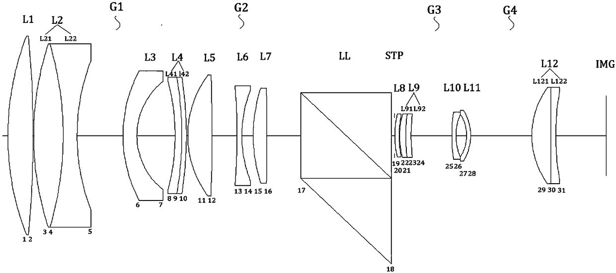
[0033] Such as figure 1 As shown, this embodiment includes in sequence from the object side to the image side: a first lens group G1 with positive refractive power, a second lens group G2 with positive refractive power, a special-shaped reentrant prism LL, a diaphragm STP, and a lens group with positive refractive power. The third lens group G3, the fourth lens group G4 with positive refractive power and the imaging surface IMG with an optical sensor.

[0034] The first lens group G1 sequentially includes: a first lens L1 with positive power, a second cemented lens L2 with negative power, a third lens L3 with negative power, and a lens with negative power The fourth cemented lens L4, wherein: the concave surface of the cemented surface of the second cemented lens L2 faces the object side, and the concave surface of the cemented surface of the fourth cemented lens L4 faces the object side.

[0035] The second lens group G2 includes in sequence: a fifth lens L5 with positive po...

Embodiment 2

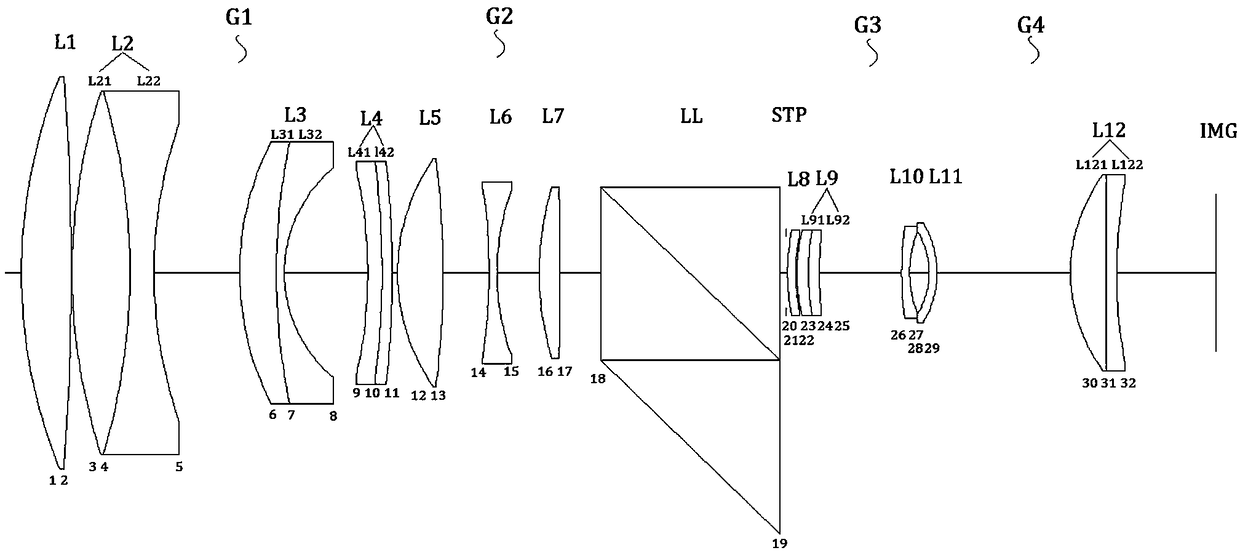
[0051] Such as image 3 As shown, compared with Embodiment 1, the third lens L3 of this embodiment is a cemented lens to further reduce the spherical aberration of the optical system.

[0052] The effective focal length of this embodiment is 100mm, and the object-image distance is 220mm.

[0053] Table 2 Lens structure parameters of this embodiment

[0054]

[0055]

[0056] Wherein the second surface of the first front lens L21 of the second cemented lens L2 is the first surface of the first rear lens L22, and the second surface of the fifth front lens L31 of the third lens L3 is the first surface of the fifth rear lens L32. surface, the second surface of the second front lens L41 of the fourth cemented lens L4 is the first surface of the second rear lens L42, and the second surface of the third front lens L91 of the ninth cemented lens L9 is the third rear lens L92. The first surface, the second surface of the fourth front lens L121 of the twelfth cemented lens L12 i...

Embodiment 3

[0064] Such as Figure 5 As shown, compared with Embodiment 1, the eighth lens L8 and the ninth cemented lens L9 of this embodiment are cemented to form a triplet lens to further reduce the astigmatism, field curvature and optical distortion of the optical system.

[0065] The effective focal length of this embodiment is 98mm, and the object-image distance is 216mm.

[0066] Table 3 Lens structure parameters of this embodiment

[0067]

[0068]

[0069] Wherein the second surface of the first front lens L21 of the second cemented lens L2 is the first surface of the first rear lens L22, and the second surface of the second front lens L41 of the fourth cemented lens L4 is the first surface of the second rear lens L42. One surface, the second surface of the eighth lens L8 is the first surface of the third front lens L91 of the ninth cemented lens L9, and the second surface of the third front lens L91 of the ninth cemented lens L9 is the first surface of the third rear lens...


PUM


Abstract

The invention relates to a short-working-distance telecentric lens. The telecentric lens sequentially comprises a first lens group, a second lens group, an abnormal-shaped turn-back prism, a diaphragm, a third lens group, a fourth lens group and an imaging plane from an object side to an image side, wherein the first lens group, the second lens group, the third lens group and the fourth lens grouphave positive focal powers, and the imaging plane is provided with an optical sensor. The telecentric lens has an imaging capacity reaching up to 8M pixel and is capable of realizing clear imaging; meanwhile, the telecentric lens can meet double telecentricity of an object space and an image space, the object space telecentricity and the image space telecentricity can meet the standards of commontelecentric lenses, and the short-working-distance telecentric lens has extremely high telecentricity level; by virtue of a special turn-back prism combination, the situation of central hot spots formed by a coaxial light source can be remarkably reduced, and the imaging problem caused by a halo produced by the light source is avoided; and the short-working-distance telecentric lens is capable ofclearly and excellently imaging light in a wavelength range of 435nm-656nm, obvious purple boundaries and chromatic dispersion are avoided, and the image quality is clear and bright.

Description

technical field [0001] The invention relates to a technology in the field of optical devices, in particular to a telecentric lens with a working distance of 100mm. Background technique [0002] The telecentric lens is mainly designed to correct the parallax of traditional industrial lenses. It can keep the magnification of the obtained image unchanged within a certain range of object distance, which is very important for the situation where the measured object is not on the same object plane. application. In the prior art, telecentric lenses are mainly divided into object-space telecentric and image-space telecentric lenses, while bi-telecentric lenses contain the common advantages of both telecentric optical paths, so the design is more difficult. , The telecentricity of the image side cannot meet a high level at the same time, and the pixel resolution is low, and the working distance is long, resulting in a larger overall lens size. In addition, the prism design of the t...

Claims


Application Information

Patent Timeline
IPC IPC(8): G02B13/00G02B13/22
CPCG02B13/0015G02B13/006G02B13/0065G02B13/22
Inventor 尚洁阳诸益炜盛亚茗
Owner JIAXING ZHONGRUN OPTICAL TECH
Learn More