Eureka AIR delivers breakthrough ideas for toughest innovation challenges, trusted by R&D personnel around the world.

Visual induced abortion device with variable viewing direction angle

A technology with variable viewing direction, applied in medical science, endoscopy, diagnosis, etc., can solve the problems of not being able to see the opening of the fallopian tube, the small field of view of the camera, and being unable to check the fundus of the uterus and the fallopian tube, so as to reduce the chance of infection and increase the chance of infection. Field of view, effect of improving efficiency

Pending Publication Date: 2018-09-25
SHANGHAI YODO MEDICAL TECH
View PDF0 Cites 5 Cited by
  • Summary
  • Abstract
  • Description
  • Claims
  • Application Information

AI Technical Summary

Problems solved by technology

Because the direction of the camera lens is on the same side as the suction port, the artificial abortion device cannot see the bottom of the uterine cavity, nor can it see the opening of the fallopian tubes, so it is impossible to check the fundus of the uterus and the fallopian tubes
Therefore, the camera field of view of the existing visual artificial flow device is small, which can only be used to attract the tissue of the uterine cavity, but cannot check the bottom of the uterine cavity and fallopian tubes.

Method used


Image

  • Visual induced abortion device with variable viewing direction angle
  • Visual induced abortion device with variable viewing direction angle
  • Visual induced abortion device with variable viewing direction angle

Examples


Embodiment Construction

[0023] A preferred embodiment will be given below, and the present invention will be described more clearly and completely in conjunction with the accompanying drawings.

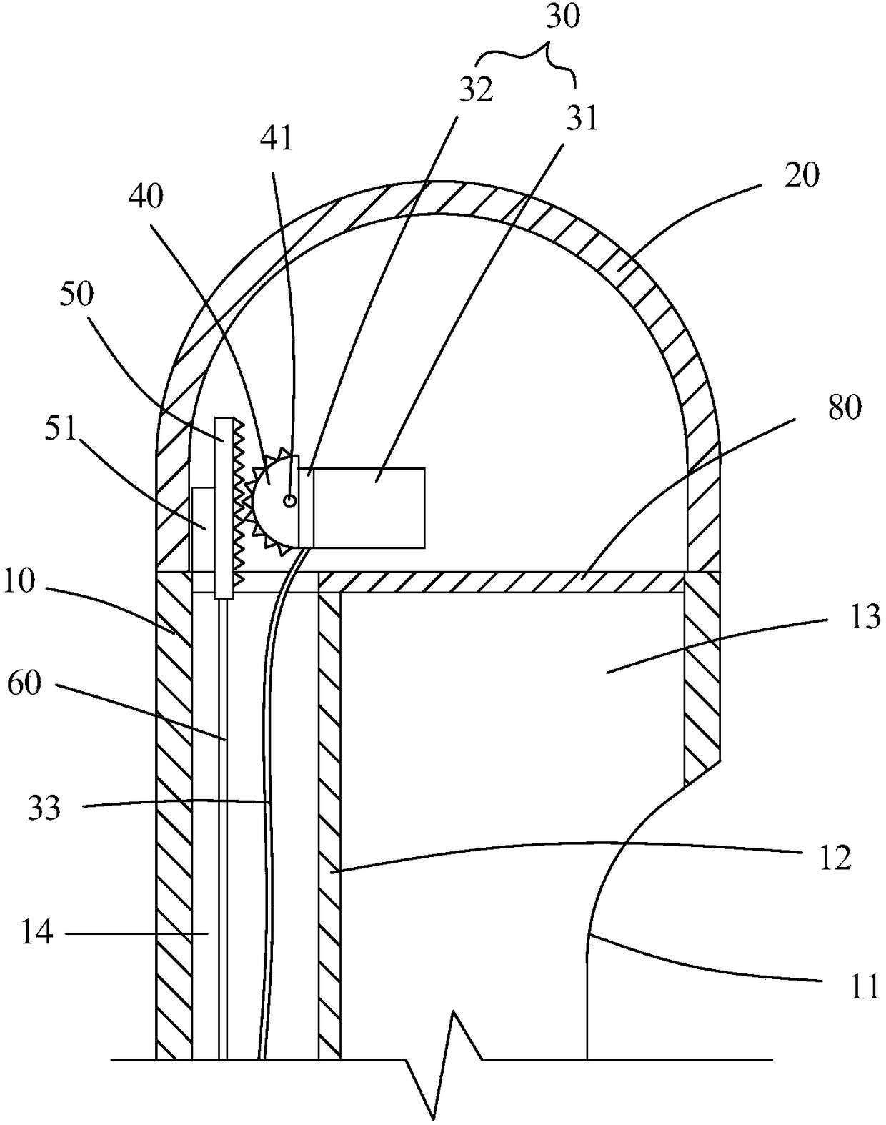
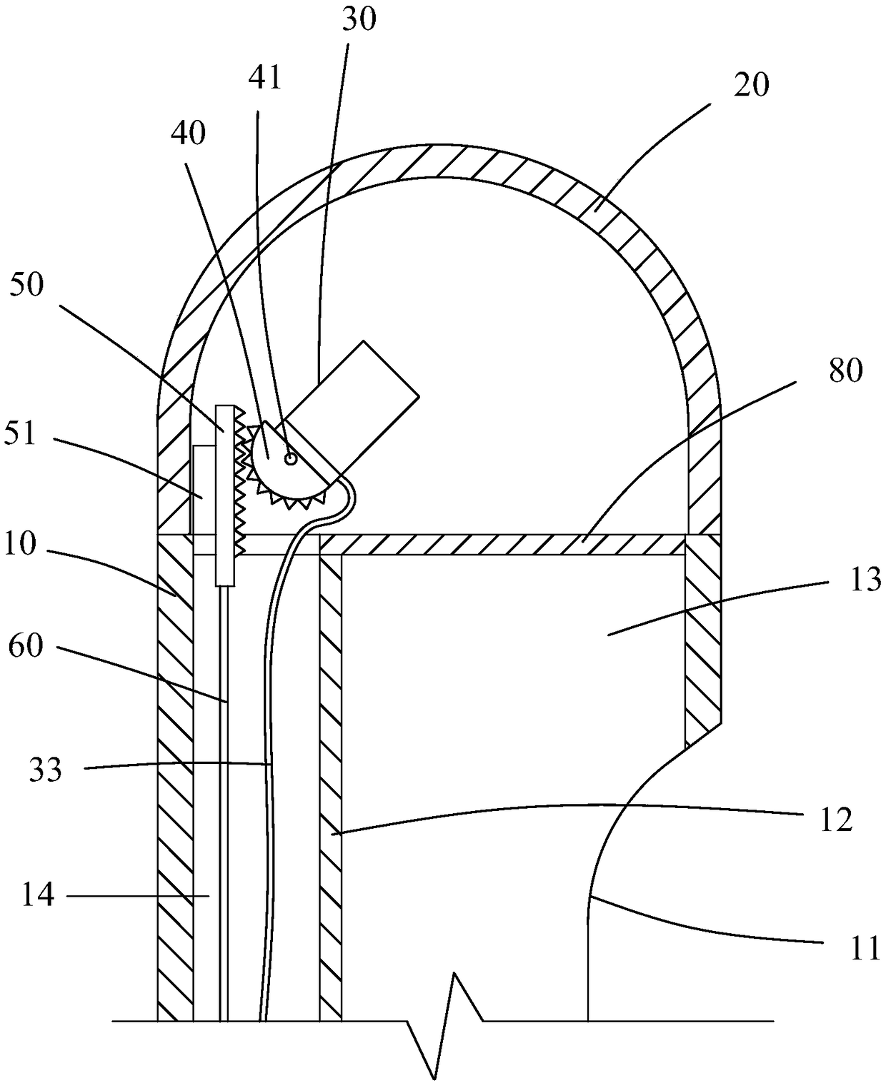
[0024] like figure 1 , figure 2 , image 3 , Figure 4 , Figure 5 and Image 6 As shown, a visual human flow device with variable viewing angle includes a suction tube 10 on which a suction port 11 is opened.

[0025] A transparent cover 20 is provided at the front end of the suction tube 10 ; a camera module 30 is provided inside the transparent cover 20 . A gear 40 is fixed on the camera module 30 , and a rotating shaft 41 is fixed on the gear 40 , and the rotating shaft 41 is pivotally connected with the transparent cover 20 .

[0026] The inner wall of the transparent cover 20 is provided with two shaft connection holes 21 , and the two ends of the rotating shaft 41 are respectively arranged in the two shaft connection holes 21 . Preferably, the inner wall of the transparent cover 20 is provided...


PUM


Abstract

The invention discloses a visual induced abortion device with a variable viewing direction angle. The visual induced abortion device comprises a suction tube, wherein a suction orifice is formed in the suction tube; a transparent cover is arranged at the front end of the suction tube; a camera module is arranged in the transparent cover; a gear is fixedly arranged on the camera module; a rotatingshaft is fixedly arranged on the gear and coupled with the transparent cover; a rack meshed with the gear is arranged outside the gear; the rack is arranged in the transparent cover in a sliding manner; a control rod used for controlling the rack to move forwards or backwards is fixedly arranged on the rack. According to the device disclosed by the invention, field of view can be greatly increased, and the device can be used for sucking tissues in the uterine cavity and examining the bottom of the uterine cavity and fallopian tube. Meanwhile, according to the device, the infection probabilityof a patient is reduced, pain of the patient is relieved, and the efficiency of an abortion operation is greatly improved.

Description

technical field [0001] The invention relates to the technical field of medical equipment, in particular to a visual human flow device with a variable viewing angle. Background technique [0002] The visible artificial flow device is used for artificial abortion and aspirating tissues in the uterine cavity. The visible people flow device includes a suction tube and a camera arranged at the front end of the suction tube, and a suction port is opened on the suction tube. Through the camera, the whole process of artificial abortion operation can be visualized. [0003] The lens direction of the camera of the existing visual human flow device is usually towards the side of the suction tube, and is located on the same side of the suction tube as the suction port. Since the lens of the camera is on the same side as the suction port, the abortion device cannot see the bottom of the uterine cavity, nor can it see the opening of the fallopian tubes, so it is impossible to check the ...

Claims


Application Information

Patent Timeline
IPC IPC(8): A61B17/42A61B1/303A61B1/04
CPCA61B1/04A61B1/303A61B17/42A61B2017/4216
Inventor 杨翔郝进争李杨
Owner SHANGHAI YODO MEDICAL TECH
Why Eureka
Eureka Blog
Learn More