Gas-liquid mixer

The technology of a gas-liquid mixer and the first flange is applied in the direction of fluid mixers, mixers, chemical instruments and methods, etc., which can solve the problems of complex structure of gas-liquid mixing devices and achieve simple structure and low manufacturing cost. Effect

Pending Publication Date: 2018-09-25
GUANGDONG XINTAILONG ENVIRONMENTAL PROTECTION GRP CO LTD
View PDF6 Cites 0 Cited by
  • Summary
  • Abstract
  • Description
  • Claims
  • Application Information

AI Technical Summary

Problems solved by technology

[0004] In view of the shortcomings of the above-mentioned prior art, the purpose of the present invention is to provide a gas-liquid mixer, which aims to solve the technical problem of complex structure of the gas-liquid mixing device used in the air flotation process in the prior art

Method used


Image

  • Gas-liquid mixer
  • Gas-liquid mixer

Examples


Embodiment Construction

[0018] The present invention provides a gas-liquid mixer. In order to make the purpose, technical solution and effect of the present invention clearer and clearer, the present invention will be further described in detail below with reference to the accompanying drawings and examples. It should be understood that the specific embodiments described here are only used to explain the present invention, not to limit the present invention.

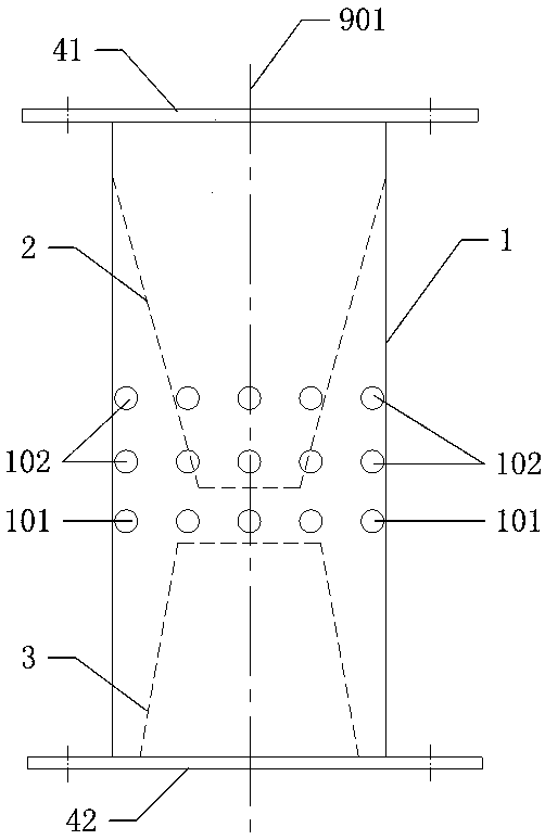
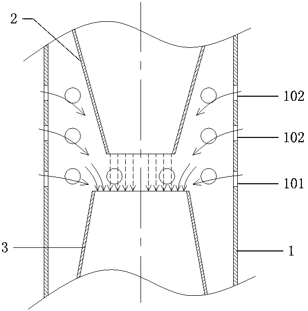
[0019] see figure 1 and figure 2 , The invention provides a gas-liquid mixer. figure 1 The constriction tube and expansion tube are drawn with dashed lines, indicating that they cannot be directly observed from the outside. figure 2 The arrow in the middle indicates the direction of air flow, figure 2 The dotted arrow in the middle shows the section of waste water between the contraction tube and the expansion tube.

[0020] Described gas-liquid mixer comprises straight pipe 1, and the inlet end of straight pipe 1 is inserted with a cont...


PUM


Abstract

The invention discloses a gas-liquid mixer. The gas-liquid mixer comprises a straight pipe, wherein a retracting pipe is inserted into an inlet end of the straight pipe and an expanding pipe is inserted into an outlet end of the straight pipe; the outlet end of the retracting pipe and the inlet end of the expanding pipe are opposite, but are not in contact; the diameter of the outlet end of the retracting pipe is less than the diameter of the inlet end of the expanding pipe; a first through hole is formed in a corresponding part, located between the retracting pipe and the expanding pipe, on the straight pipe. The gas-liquid mixer provided by the invention is simple in structure and low in manufacturing cost; the gas-liquid mixer is easily connected with an upstream pipeline and a downstream pipe and is small in occupied area.

Description

technical field [0001] The invention relates to the technical field of mixing equipment, in particular to a gas-liquid mixer. Background technique [0002] The air flotation process is often used in wastewater treatment, mainly by introducing air into the wastewater, so that highly dispersed micro-bubbles are formed in the wastewater, and the particles in the wastewater adhere to the bubbles to form flocs with an apparent density lower than water and float to the water surface , for further separation. In order to realize the mixing of waste water and air, a mixing tank is mainly provided in the prior art, and then the waste water is passed into the mixing tank through a water pump, and the air is passed into the mixing tank through an air pump. However, the disadvantages of such an arrangement mainly include a large number of equipment, complicated piping, and a large footprint. [0003] It can be seen that the prior art still needs to be improved and enhanced. Contents...

Claims


Application Information

Patent Timeline
Patent Type & Authority Applications(China)
IPC IPC(8): B01F5/02C02F1/24
CPCC02F1/24B01F25/27B01F25/21B01F2101/305
Inventor 辛永光向乾柱
Owner GUANGDONG XINTAILONG ENVIRONMENTAL PROTECTION GRP CO LTD
Why Eureka
Try Eureka