
Steel belt uniform-speed edge-scraping equipment

A technology for edge scraping and steel strip, applied in metal processing equipment, measuring/indicating equipment, other manufacturing equipment/tools, etc., can solve problems such as temperature rise of scraping tool, affecting steel strip material, waste of resources, etc., to prevent Reduce scraping quality, ensure scraping quality and prolong service life

Pending Publication Date: 2018-09-25
XINXIANG HUIHUANG SPRING
View PDF0 Cites 3 Cited by
  • Summary
  • Abstract
  • Description
  • Claims
  • Application Information

AI Technical Summary

Problems solved by technology

[0002] At present, the motor of the strip edge scraping device is installed on the take-up pulley, and the motor is provided with a speedometer and a controller, and the speedometer and the controller keep the motor running at a constant speed. With the increase of the number of turns, when the take-up pulley maintains a constant speed, the speed of the unwinding pulley increases gradually, and the temperature of the edge scraping tool gradually increases. If the temperature is too high, the edge scraping tool may even burn out. In addition, the steel The temperature of the belt will also gradually increase, too high temperature will affect the material of the steel belt, and the effect is not good
[0003] At the same time, when starting to scrape the steel belt, since the take-up pulley is a power pulley, it is necessary to first fix the steel strip to be scraped through the steel strip edge scraping device on the take-up pulley, and then pull the steel belt by the take-up pulley. The belt is moved, the distance between the existing scraper and the take-up wheel is very long, and the steel belt between this distance cannot be scraped, resulting in a waste of resources

Method used


Image

  • Steel belt uniform-speed edge-scraping equipment
  • Steel belt uniform-speed edge-scraping equipment
  • Steel belt uniform-speed edge-scraping equipment

Examples


Embodiment

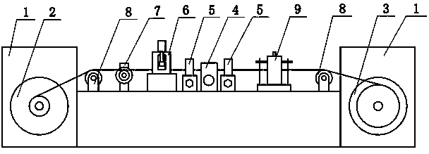
[0026] Example: see figure 1 , figure 2 , image 3 , Figure 4 , Figure 5 , Figure 6 , Figure 7 , Figure 8 , Figure 9 with Figure 10 , in the picture, 1-frame, 2-take-up pulley, 3-release pulley, 4-knife holder, 5-limiting wheel, 6-auxiliary wheel, 7-speed measuring roller, 8-guiding wheel, 9-leveling wheel;

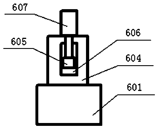
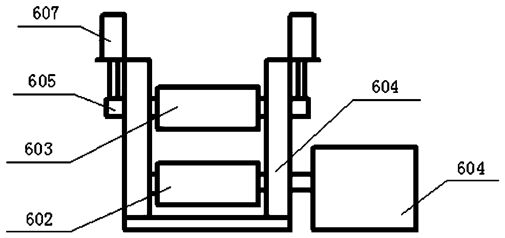
[0027] 601-auxiliary motor, 602-auxiliary wheel one, 603-auxiliary wheel two, 604-auxiliary bracket, 605-slider, 606-slide, 607-auxiliary cylinder;

[0028] 401-cutter head Ⅰ, 402-cutter head Ⅱ, 403-guide rail, 404-baffle plate, 405-moving handle;

[0029] 501-limiting wheel bracket, 502-removable limiting wheel, 503-limiting wheel bolt, 504-groove, 5021-detachable limiting wheel bracket, 5022-limiting wheel one, 5023-limiting wheel two;

[0030] 901-leveling wheel bracket, 902-bolt, 903-upper leveling wheel fixing plate, 904-upper leveling wheel, 905-lower leveling wheel, 906-adjusting bolt.

[0031] Steel belt uniform speed scraping equipment, includ...


PUM


Abstract

The invention discloses steel belt uniform-speed edge-scraping equipment. The steel belt uniform-speed edge-scraping equipment comprises a machine frame; a belt reeling wheel and a belt unreeling wheel are arranged at the two ends of the machine frame respectively; the belt reeling wheel is connected with a motor; a knife rest is arranged in the middle of the machine frame; a scraping knife is arranged on the knife rest; limiting wheels are arranged on the machine frame on the two sides of the scraping knife; the limiting wheels comprises a reeling end limiting wheel and an unreeling end limiting wheel; an auxiliary wheel, a speed measuring roller and a guide wheel are arranged on the machine frame between the unreeling end limiting wheel and the belt unreeling wheel sequentially; a flattening wheel and a guide wheel are arranged on the machine frame between the unreeling end limiting wheel and the belt unreeling wheel sequentially; the motor is separated from a speed measuring device;the speed measuring device is arranged between the belt reeling wheel and the belt unreeling wheel and can monitor the motion speed of the steel belt at any time; the auxiliary wheel is provided to increase the utilization rate of the steel belt and reduce waste of the steel belt.

Description

Technical field: [0001] The invention relates to a steel belt edge scraping machine, in particular to a steel belt uniform speed edge scraping equipment. Background technique: [0002] At present, the motor of the strip edge scraping device is installed on the take-up pulley, and the motor is provided with a speedometer and a controller, and the speedometer and the controller keep the motor running at a constant speed. With the increase of the number of turns, when the take-up pulley maintains a constant speed, the speed of the unwinding pulley increases gradually, and the temperature of the edge scraping tool gradually increases. If the temperature is too high, the edge scraping tool may even burn out. In addition, the steel The temperature of the belt will also gradually increase, and the high temperature will affect the material of the steel belt, and the effect is not good. [0003] At the same time, when starting to scrape the steel belt, since the take-up pulley is a ...

Claims


Application Information

Patent Timeline
IPC IPC(8): B23D79/02B23D79/10B23Q7/00B23Q7/05B23Q17/00B23Q15/013B23P23/04
CPCB23D79/02B23D79/10B23P23/04B23Q7/00B23Q7/05B23Q15/013B23Q17/00
Inventor 元宇飞张幸福
Owner XINXIANG HUIHUANG SPRING
Learn More