

Optical scanning double-layer light guide encoder
A technology of optical scanning and optical encoder, which is applied in the field of encoders, can solve the problem that the resolution of light-guiding encoders cannot be significantly improved, and achieve the effect of avoiding light diffraction and improving resolution
- Summary
- Abstract
- Description
- Claims
- Application Information
AI Technical Summary
Problems solved by technology
Method used
Image

Examples
no. 1 Embodiment
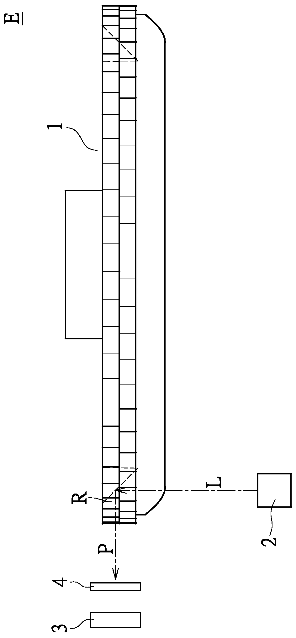
[0070] Please refer to Figures 12 to 15 as shown, Figures 12 to 15 When the double-layer light guide grating wheel 1 of the optical scanning double-layer light guide encoder E provided by the first embodiment of the present invention rotates to the first, second, third and fourth positions, the parallel light beam Or a partial schematic diagram of the relationship between the near-parallel light beam P and the light sensing module 3 .
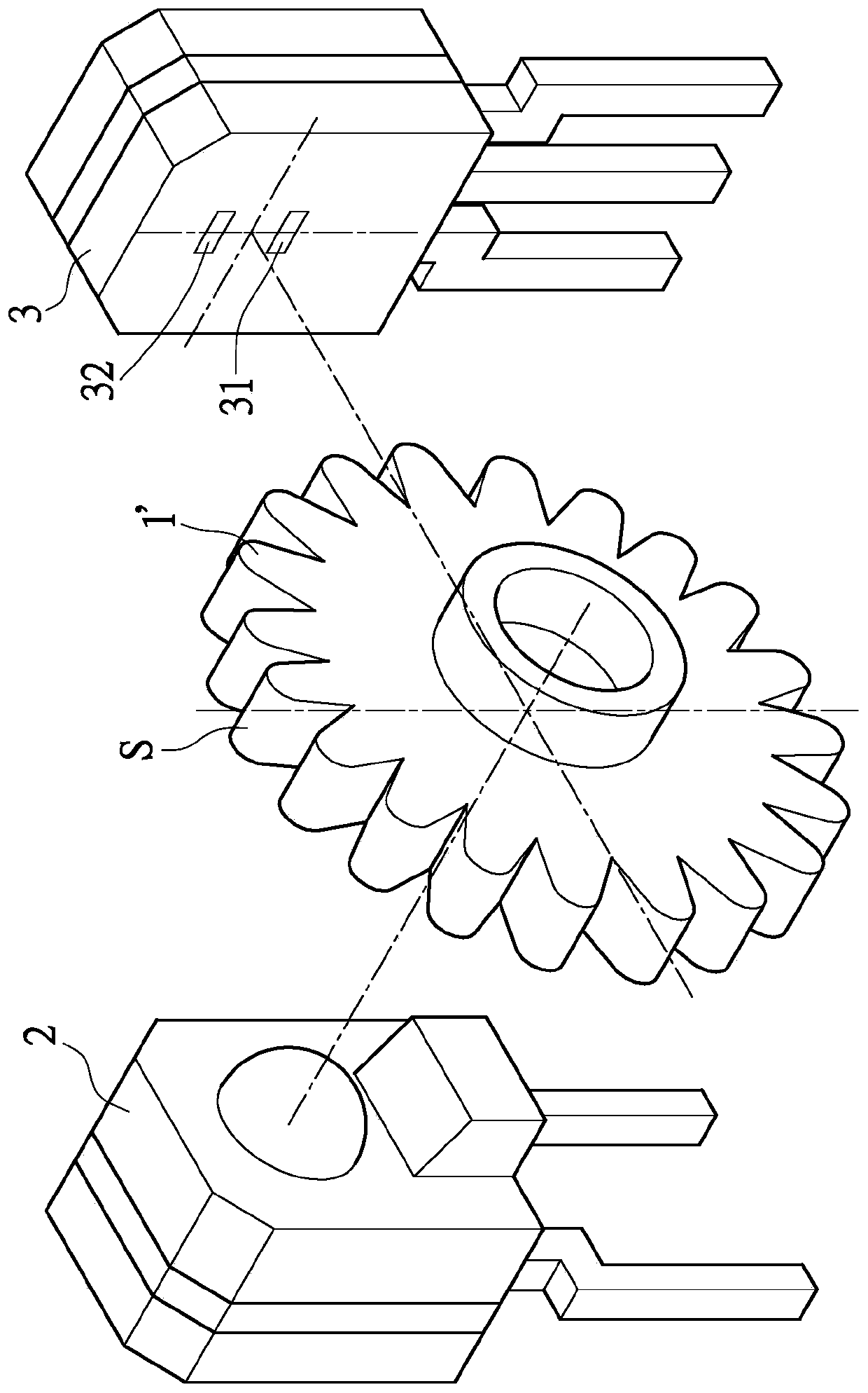
[0071] Specifically, as Figure 12 As shown, the light sensing module 3 includes a strip-shaped first sensing element 31' and a second sensing element 32', the two sensing elements have the same width D1, and their two ends are aligned with each other, The photo-sensing module 3 also has a width D1. A grating 4 with a width greater than D1 is further provided between the photo-sensing module 3 and the double-layer light-guiding grating wheel 1, which is used to shield certain areas of the first sensing element 31' and the second sensing el...
no. 2 Embodiment
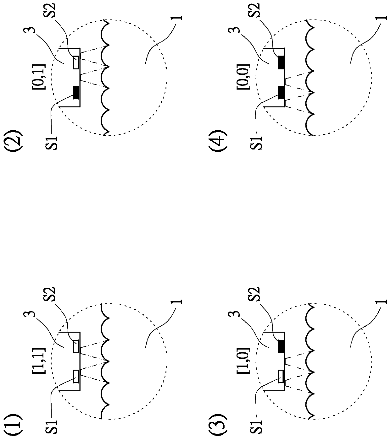
[0079] Next, see Figures 16 to 20 , Figures 16 to 19 The double-layer light guide grating wheel 1 of the optical scanning double-layer light guide encoder E provided by the second specific embodiment of the present invention is in different positions, that is, the first position (1) to the fourth position (4) , a partial schematic diagram of the relationship between the parallel light beam or the near-parallel light beam P and the light sensing module 3, and Figure 20 The schematic diagram of the signal generated by the light sensing module in this embodiment after receiving the light beam.
[0080] exist Figures 16 to 19 Among them, the first sensing element 31' and the second sensing element 32' of the light sensing module 3 expose the first bare sensing region 31 and the second sensing area 31 through the first opening 41 and the second opening 42 of the grating 4 respectively. Two exposed sensing regions 32 . The first bare sensing region 31 and the second bare sen...
no. 3 Embodiment
[0088] Next, Figure 21 and 22 A schematic diagram further illustrating the generation of encoded signals by the optical scanning double-layer light guide encoder E provided in the third specific embodiment of the present invention. in particular, Figure 21 When the double-layer light guide grating wheel 1 of the optical scanning double-layer light guide encoder E provided by the third embodiment of the present invention is in the first position (1), it is parallel to the parallel light beam or the near-parallel light beam P and the light sensor A partial schematic diagram of the relationship between the measurement modules 3, and Figure 22 for Figure 21 A schematic diagram of the signal generated by the light sensing module 3 used after receiving the light beam.
[0089] Different from the previous embodiments, in this embodiment, the light sensing module 3 is composed of a first sensing element 31', a second sensing element 32', a third sensing element 33' and a fourt...
PUM
 Abstract
Description
Claims
Application Information