
A Design Method of Uniform Flow Guide Components Based on Exhaust Duct Area Control

A technology of flow guide components and design methods, applied in geometric CAD, special data processing applications, etc., can solve problems such as uneven exhaust, and achieve the effect of avoiding debugging work and high adaptability

Active Publication Date: 2021-10-15
TONGJI UNIV
View PDF7 Cites 0 Cited by
  • Summary
  • Abstract
  • Description
  • Claims
  • Application Information

AI Technical Summary

Problems solved by technology

[0004] The purpose of the present invention is to provide a method for designing a uniform flow guide member based on the area control of the exhaust duct to solve the problem of uneven exhaust in the above-mentioned prior art

Method used


Image

  • A Design Method of Uniform Flow Guide Components Based on Exhaust Duct Area Control
  • A Design Method of Uniform Flow Guide Components Based on Exhaust Duct Area Control
  • A Design Method of Uniform Flow Guide Components Based on Exhaust Duct Area Control

Examples


Embodiment Construction

[0043] The present invention is described in further detail below in conjunction with embodiment.

[0044] First, explain or define the terms involved:

[0045] Exhaust duct area control: Exhaust duct area control refers to the design of atlases in accordance with national regulations or relevant national building standards to determine the size of residential centralized flue and branch pipes.

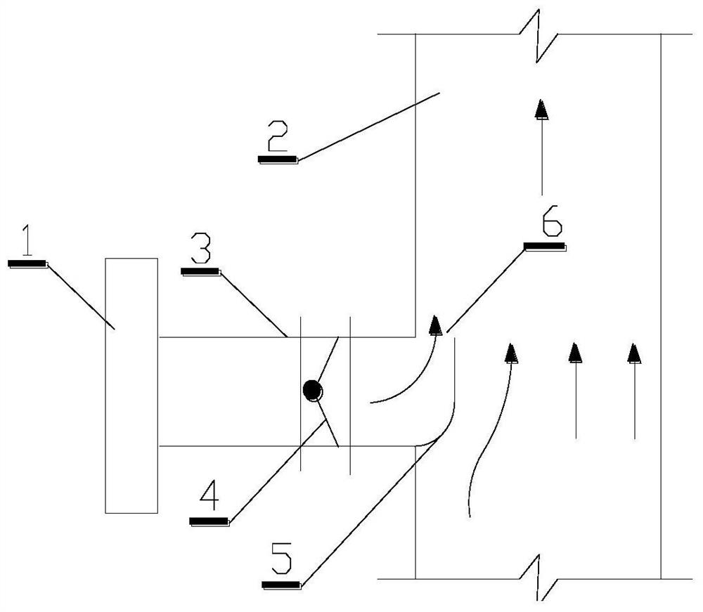
[0046] see figure 1 , is a schematic diagram of the installation position of a certain layer of flow guide members in the centralized air duct according to the embodiment of the present invention. It includes a range hood 1, an exhaust duct 2, a user branch pipe 3, a check valve 4, and a flow guide member 5; the range hood 1 and the exhaust duct 2 are connected through the user branch pipe 3, so that the oil fume absorbed by the range hood passes through the branch pipe, exhaust The air duct is discharged, and the check valve 4 is installed on the user branch pipe 3 to prevent the o...


PUM


Abstract

A method for designing a uniform flow guide member based on area control of an exhaust duct, comprising the following steps: determining the resistance characteristic of the flow guide member, and fitting the resistance characteristic curve or formula of the flow guide member by combining CFD numerical calculation and experiment; According to the resistance relationship of each loop of the exhaust system, calculate the required resistance characteristics of the flow guide structure; according to the required resistance characteristics of the flow guide member, determine the flow guide member in the resistance characteristic curve or formula obtained in advance The required size to complete the design of the uniform exhaust system. The invention proposes a new calculation method for a uniform exhaust system, which can accurately ensure the flow uniformity of each tuyere of the exhaust system from the design stage.

Description

technical field [0001] The invention belongs to the technical field of ventilation, and relates to a design method of a uniform flow guiding member based on the area control of an exhaust duct. Background technique [0002] In the centralized smoke exhaust system of high-rise residential kitchens, the smoke exhaust pipes of each user are connected to the flue shaft to form a multi-power source pipe network system. The pressure head of the range hood of each user is basically the same, and the resistance to be overcome by the user's pressure head includes the pressure loss on the user side and the pressure loss consumed in the shaft. The lower the users, the more pressure they consume on the side of the flue shaft, so the pressure drop on the user side decreases, and the amount of smoke exhausted by the users decreases accordingly. Therefore, this kind of multi-power source confluence system is prone to the situation that the upper user has a large amount of smoke exhaust, a...

Claims


Application Information

Patent Timeline
Patent Type & Authority Patents(China)
IPC IPC(8): G06F30/13
CPCG06F30/13
Inventor 高军侯玉梅曹昌盛王依蕊
Owner TONGJI UNIV
Learn More