
Round wire L-shaped locking connector and connection method thereof

A technology of connectors and round wires, which is applied in the field of round wire L-shaped locking connectors and their connections, and can solve the problem of relatively large differences in the linear expansion coefficients between wire connectors and wires, small contact areas between wires and connectors, and wire bolts. Problems such as plastic deformation at the crimping point, to avoid electrochemical reactions, improve connection reliability, and increase the effect of connection contact area

Pending Publication Date: 2018-09-25
GUIZHOU POWER GRID CO LTD
View PDF3 Cites 3 Cited by
  • Summary
  • Abstract
  • Description
  • Claims
  • Application Information

AI Technical Summary

Problems solved by technology

[0005] Although the wire connection of the wire bolt crimping connector is simple and easy to implement, due to the difference between the material of the connector and the wire, the wire connector has serious yield deformation after installation, the contact area between the wire and the connector is small, and The difference between the linear expansion coefficient of the wire connector and the wire is relatively large. After a long period of operation, after many cycles of cooling and heating, the crimping part of the wire bolt continues to undergo plastic deformation, resulting in loosening of the gap, and the entry of air, etc. makes the connection body compressed. The junction surface is oxidized, which increases the contact resistance of the conductor connector and causes heat failure

Method used


Image

  • Round wire L-shaped locking connector and connection method thereof
  • Round wire L-shaped locking connector and connection method thereof
  • Round wire L-shaped locking connector and connection method thereof

Examples


Embodiment 1

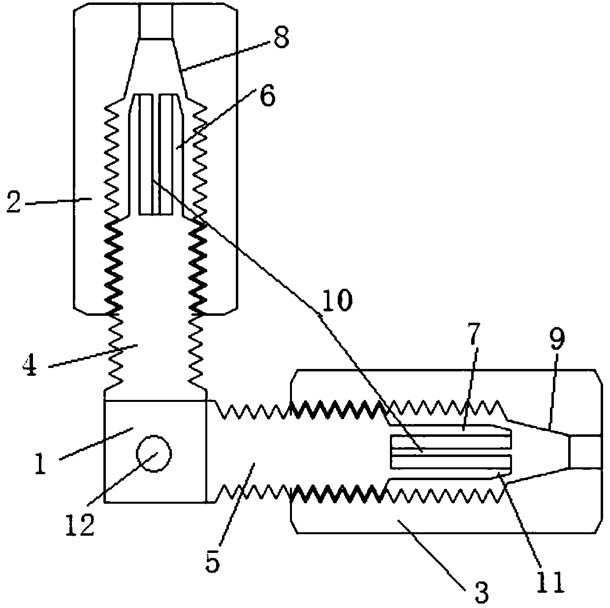
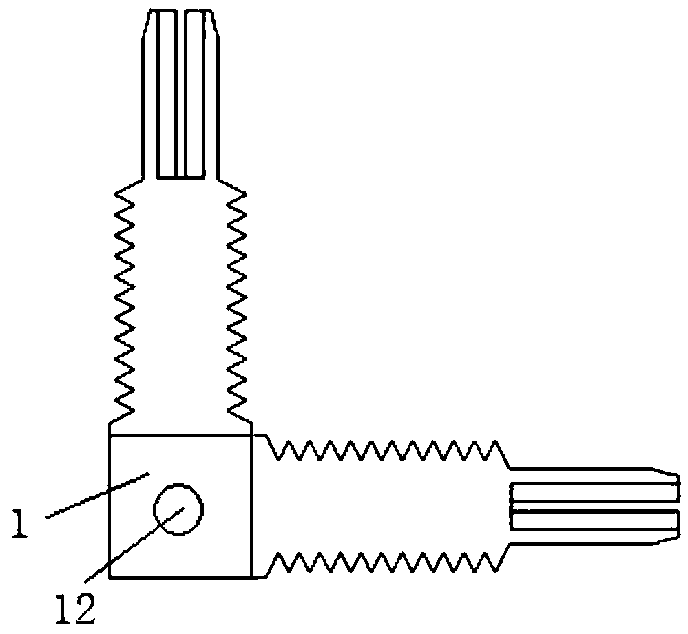
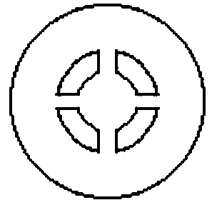
[0063] Embodiment 1: as Figure 1-Figure 8As shown, an L-shaped locking connector for round wires includes a conductive connecting body 1, an input locking nut 2 and an output locking nut 3, and the two ends of the connecting body 1 are respectively provided with mutually perpendicular input screw parts 4 and The output screw part 5, the ends of the input screw part 4 and the output screw part 5 are respectively provided with an input locking tube 6 and an output locking tube 7, and the inner holes of the outer ends of the input locking nut 2 and the output locking nut 3 are respectively provided There are input locking cone section 8 and output locking cone section 9, both input locking tube 6 and output locking tube 7 are provided with U-shaped opening 10, input locking nut 2 and output locking nut 3 are respectively connected to On the input screw part 4 and the output screw part 5, the input locking cone segment 8 and the output locking cone segment 9 are respectively sque...


PUM


Abstract

The invention discloses a round wire L-shaped locking connector and a connection method thereof. The round wire L-shaped locking connector comprises an electrically conductive connecting body, an input locking nut and an output locking nut; two ends of the connecting body are respectively provided with an input screw portion and an output screw portion which are perpendicular to each other; an input locking tube and an output locking tube are arranged on ends of the input screw portion and the output screw portion respectively; an input locking cone section and an output locking cone section are arranged in inner holes formed in outer ends of the input locking nut and the output locking nut; U-shaped openings are formed in the input locking tube and the output locking tube; the input locking nut and the output locking nut are connected to the input screw portion and the output screw portion respectively; and the input locking cone section and the output locking cone section are pressedon the input locking tube and the output locking tube respectively. The invention can quickly and vertically connect two round wires, can achieve reversing connection, can reduce the resistance, canprevent gaps, loosening and oxidation of a joint conductor contact surface after the hot and cold cycle of the connector, and can improve the connection reliability of the joint.

Description

technical field [0001] The invention belongs to the technical field of power connection equipment, and in particular relates to an L-shaped locking connector for round wires and a connection method thereof. Background technique [0002] In the previous connection of round wires, wire bolt crimp connectors are usually used for connection. This type of connector has a simple structure, is easy to install, and does not require high quality operators. [0003] The existing L-shaped wire connector includes a wire bolt crimping connection body and two wire pressing bolts. The connection body is processed with an input wire connection hole and a lateral compression bolt hole, a vertical output wire connection hole and a lateral compression bolt hole. [0004] Such as Figure 9-11 As shown, the connection body and bolts of the wire bolt crimping connector are generally made of stainless steel, the wire connection hole is horizontally processed with a threaded hole, and the compress...

Claims


Application Information

Patent Timeline
IPC IPC(8): H01R4/50H01R11/01H01R11/09H01R43/00
CPCH01R4/5025H01R11/01H01R11/09H01R43/00
Inventor 张仁奇
Owner GUIZHOU POWER GRID CO LTD
Learn More