
Separator and sand mill

A technology of separator and sand mill, which is applied in the direction of grain processing, etc., can solve the problem of secondary metal pollution of slurry, achieve the effect of convenient assembly and expand the scope of application

Inactive Publication Date: 2018-09-28
JIANGSU FEILU HEAVY MACHINERY MFG CO LTD
View PDF4 Cites 0 Cited by
  • Summary
  • Abstract
  • Description
  • Claims
  • Application Information

AI Technical Summary

Problems solved by technology

[0005] The technical problem to be solved by the present invention is to provide a separator for the problem that the metal separator in the prior art is likely to cause secondary metal pollution to the slurry

Method used


Image

  • Separator and sand mill
  • Separator and sand mill
  • Separator and sand mill

Examples


Embodiment Construction

[0032] In order to make the technical problems, technical solutions and beneficial effects solved by the present invention clearer, the present invention will be further described in detail below in conjunction with the accompanying drawings and embodiments. It should be understood that the specific embodiments described here are only used to explain the present invention, not to limit the present invention.

[0033] In describing the present invention, it should be understood that the terms "length", "width", "thickness", "upper", "lower", "front", "rear", "left", "right", " The orientations or positional relationships indicated by "vertical", "horizontal", "top", "bottom", "inner" and "outer" are based on the orientations or positional relationships shown in the drawings, and are only for the convenience of describing the present invention and Simplified descriptions, rather than indicating or implying that the device or element referred to must have a particular orientation...


PUM

PropertyMeasurementUnit
Thicknessaaaaaaaaaa

Abstract

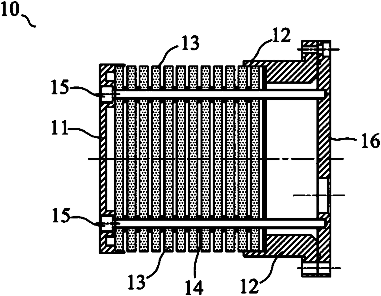
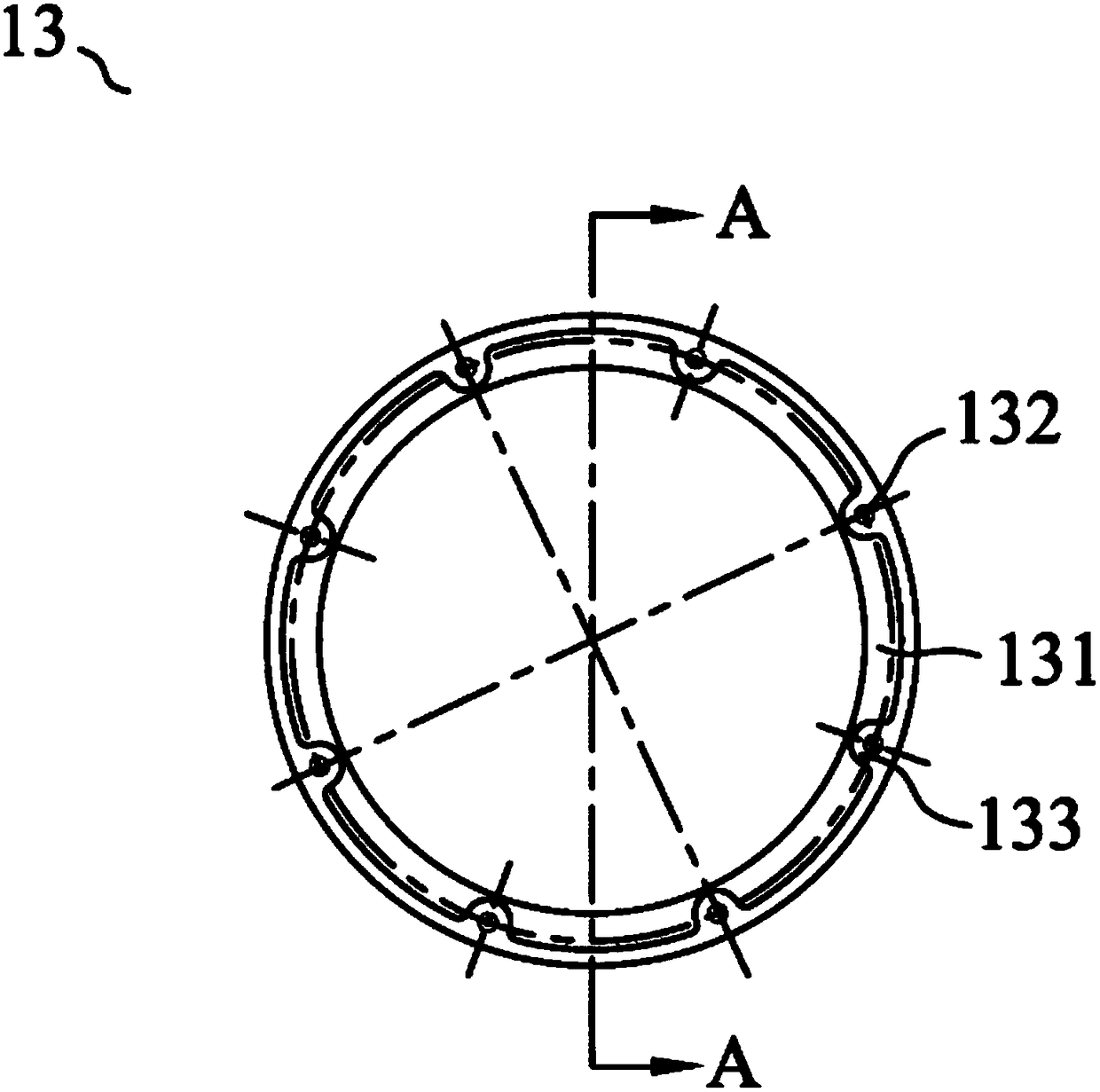
In order to overcome the problem that a metal separator is easy to cause secondary metallic pollution to slurry in the prior art, the invention provides a separator, which comprises a screen mesh gland, a screen mesh pedestal, an end cap and multiple discs. The screen mesh gland, the multiple discs, the screen mesh pedestal and the end cap are arranged in order. The screen mesh gland and the end cap are fixed with each other. The multiple discs are successively overlapped in the direction from the screen mesh gland to the screen mesh pedestal. A pad is arranged between two adjacent discs and isolates two adjacent discs so as to form a filter seam. The screen mesh gland, the screen mesh pedestal and the discs are all ceramic. The end cap has a discharge port which penetrates through the endcap. Meanwhile, the invention also provides a sand mill with the application of the separator. The separator provided by the invention will not cause secondary metallic pollution to slurry when in use. In addition, according to needs, thickness of the pads is adjusted arbitrarily so as to regulate width of the filter seam. The separator of the invention is convenient to operate and has extensiveapplicability.

Description

technical field [0001] The invention relates to a separator and a sand mill using the separator. Background technique [0002] At present, most of the sand mills used in the industry are disc type and pin pin type. The basic principle is: media for grinding such as zirconium beads, glass beads, etc. Or the rod pin moves the medium in the cylinder to make the medium move relative to each other, so that the material to be ground passes through the medium to achieve the crushing effect. The higher the relative speed of the grinding medium, the greater the collision force and the better the grinding fineness; the mode of action of the disc and pin-type sand mill makes the effect of the relative movement of the grinding medium not very ideal, so the material to be ground The fineness is difficult to reach the nanometer level. [0003] At present, improving the grinding efficiency and grinding product precision and developing the application field of the sand mill are the resear...

Claims


Application Information

Patent Timeline
IPC IPC(8): B02C17/18B02C23/08B02C17/16
CPCB02C17/183B02C17/16B02C17/1815B02C17/182B02C23/08
Inventor 张宗良
Owner JIANGSU FEILU HEAVY MACHINERY MFG CO LTD
Learn More