Pouring mechanical arm

A technology of manipulator and moving plate, applied in the field of manipulator, can solve the problems of small adjustment range of manipulator, limited range of pouring, inconvenient production operation, etc., so as to meet various needs, increase the range of pouring, and the range of adjustment wide effect

Active Publication Date: 2018-09-28
江西浩瑞建设工程有限公司
View PDF7 Cites 3 Cited by
  • Summary
  • Abstract
  • Description
  • Claims
  • Application Information

AI Technical Summary

Problems solved by technology

Although the existing pouring robot arm reduces the problem of labor intensity by adding a single-arm crane, it has the problem of limited use range. Due to its single structure, when the single-arm crane is fixed, the pouring range Limited, it will be very inconvenient during production operations. At the same time, the adjustment range of the mechanical arm is small, which cannot meet the needs of pouring. In addition, it is inconvenient to move the pouring barrel in the pouring of raw materials. Therefore, a kind of Pouring robotic arm to solve the above problems

Method used


Image

  • Pouring mechanical arm
  • Pouring mechanical arm
  • Pouring mechanical arm

Examples


Embodiment Construction

[0020] The following will clearly and completely describe the technical solutions in the embodiments of the present invention with reference to the accompanying drawings in the embodiments of the present invention. Obviously, the described embodiments are only some, not all, embodiments of the present invention.

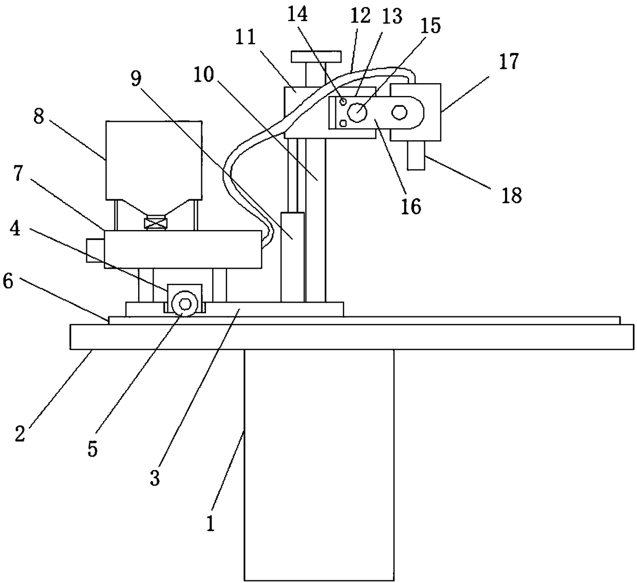
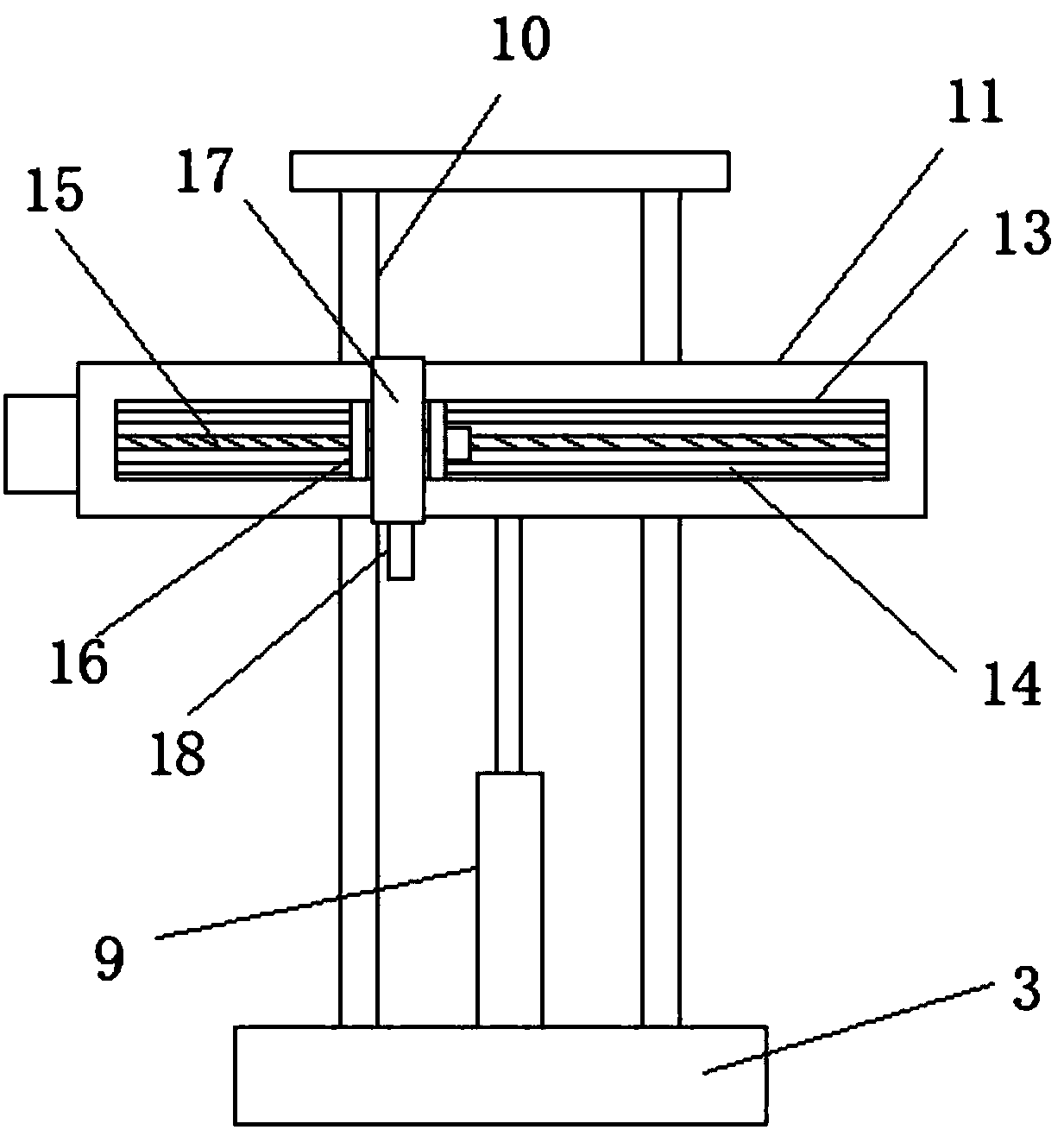
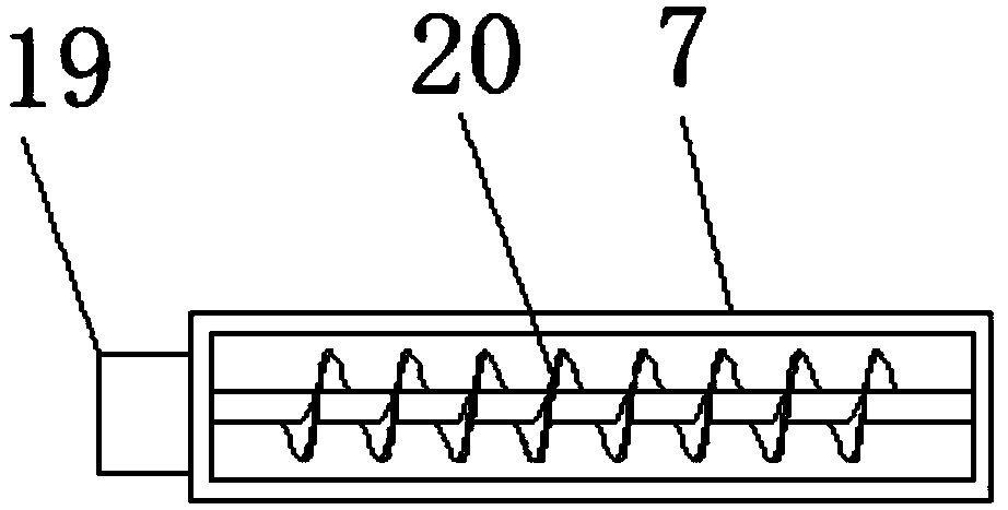
[0021] refer to Figure 1-3 , a pouring mechanical arm, including a support platform 1, the top of the support platform 1 is fixedly connected with a horizontal plate 2, a moving plate 3 is slidably installed on the horizontal plate 2, a first motor 4 is fixedly installed on the moving plate 3, and the first motor The output shaft of 4 is provided with a gear 5, the top of the horizontal plate 2 is fixedly connected with a rack 6, the rack 6 meshes with the gear 5, the gear 5 is located above the rack 6, and the top of the moving plate 3 is fixedly installed with a push tube 7. A raw material box 8 is fixedly installed on the top of the push tube 7, a delivery hose 1...


PUM


Abstract

The invention discloses a pouring mechanical arm. The pouring mechanical arm comprises a supporting table, wherein the top of the supporting table is fixedly connected to a transverse plate; a movableplate is arranged on the transverse plate in a sliding manner; a first motor is fixedly arranged on the movable plate; a gear is arranged on an output shaft of the first motor in a sleeving manner; the top of the transverse plate is fixedly connected to a rack which is meshed with the gear; the gear is located above the rack; a pushing pipe is fixedly arranged on the top of the movable plate; a raw material box is fixedly arranged on the top of the pushing pipe; one end of the pushing pipe is fixedly connected to a conveying hose; an air cylinder and a guide pillar are fixedly arranged on thetop of the movable plate; a lifting table is horizontally arranged on the guide pillar in a sliding manner; a piston rod of the air cylinder is fixedly connected to the bottom of a lifting table; anda sliding chute is formed in one side of the lifting table. The pouring mechanical arm facilities the conveying of poured raw materials and causes pouring to be relatively convenient; meanwhile, themovement of the mechanical arm at the arbitrary position of space and the adjustment of the pouring angle enlarge the pouring range; and the multiaspect requirements on pouring are met.

Description

technical field [0001] The invention relates to the technical field of mechanical arms, in particular to a pouring mechanical arm. Background technique [0002] Casting is a process in which liquid metal is poured into a casting cavity adapted to the shape of the part, cooled and solidified, and cleaned to obtain a casting with a predetermined shape, size and performance. The material to be cast is mostly a metal that was originally solid but heated to a liquid state, such as copper, iron, aluminum, tin, lead, etc., and the material of the mold can be sand, metal or even ceramics. Depending on the requirements, the methods used will vary. Although the existing pouring robot arm reduces the problem of labor intensity by adding a single-arm crane, it has the problem of limited range of use. Due to its single structure, when the single-arm crane is fixed, the pouring range Limited, it will be very inconvenient during production operations. At the same time, the adjustment ran...

Claims


Application Information

Patent Timeline
Patent Type & Authority Applications(China)
IPC IPC(8): B22D35/00B25J11/00
CPCB22D35/00B22D35/04B25J11/00
Inventor 孙莉莉
Owner 江西浩瑞建设工程有限公司
Why Eureka
Try Eureka