A process method for fully automatic welding of the corrugated wall of the fuel tank of the distribution transformer by a robot

A fully automatic welding and process method technology, applied in the direction of welding equipment, welding equipment, auxiliary welding equipment, etc., can solve the problems of time-consuming, time-consuming and labor-intensive, unstable weld quality, etc. Beautiful appearance, elimination of welding holes and suppression of leakage points

Active Publication Date: 2020-07-14
山东泰开箱变有限公司
View PDF6 Cites 0 Cited by
  • Summary
  • Abstract
  • Description
  • Claims
  • Application Information

AI Technical Summary

Problems solved by technology

[0009] 1. Manual welding
The quality of the weld seam is greatly affected by the skills of the personnel, and the quality of the weld seam is unstable. During the welding process, the entire fuel tank needs to be turned over many times, which is time-consuming and laborious.
[0010] 2. The corrugated wall needs to be spot-welded by a special person, and it will be fully welded after welding, which is labor-intensive and time-consuming
[0011] 3. There are leakage points (welding defects such as welding holes, local thermal deformation, and virtual welding) after the skeleton and the corrugated wall are welded, and special personnel are required to suppress the leak and repair all the leaking positions

Method used


Image

  • A process method for fully automatic welding of the corrugated wall of the fuel tank of the distribution transformer by a robot
  • A process method for fully automatic welding of the corrugated wall of the fuel tank of the distribution transformer by a robot
  • A process method for fully automatic welding of the corrugated wall of the fuel tank of the distribution transformer by a robot

Examples


Embodiment Construction

[0045] The preferred embodiments of the present invention will be described in detail below in conjunction with the accompanying drawings, so that the advantages and features of the present invention can be more easily understood by those skilled in the art, so as to define the protection scope of the present invention more clearly.

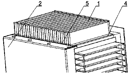
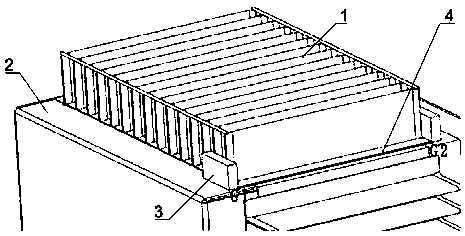
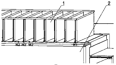
[0046] refer to figure 1 , figure 2 As shown, the present invention provides a robotic automatic welding method for the corrugated wall of the distribution transformer fuel tank. The position of the contact line between the corrugated wall 1 and the fuel tank frame 2 is preset for the straight weld 4 and the side weld 5, and the contact line parallel to the fins The weld at the position is a straight weld 4, and the position of the contact line perpendicular to the fin is a side weld 5;

[0047] The process method comprises the following steps:

[0048] S1. Assemble and install the corrugated wall 1 and the fuel tank frame 2 on the welding too...


PUM


Abstract

The invention discloses a technological method for fully-automatically welding a distribution transformer oil tank and a corrugated wall by utilizing a robot. The technological method comprises the following steps: determining the quantity of side-weld locating points according to the length of the corrugated wall and the quantity of fins, sequentially touching side surfaces and end surfaces of the fins at the locating points as well as the upper plane of an oil tank framework by utilizing a welding wire which extends out of an arm welding gun of the welding robot so as to acquire a first locating coordinate set, connecting a plurality of locating point coordinates so as to form a side-weld welding path, and carrying out side-weld welding by utilizing the arm welding gun; arranging positioning-stopping blocks on two sides of a direct-weld position, and touching side surfaces and outer end surfaces of the positioning-stopping blocks at the direct-weld position as well as the upper planeof the oil tank framework by utilizing the welding wire which extends out of the arm welding gun so as to acquire a second locating coordinate set; and calculating two end-point coordinates of a direct-weld welding path according to the second locating coordinate set, and connecting the end-point coordinates to form the direct-weld welding path. According to the technological method disclosed bythe invention, welds between the corrugated wall and the distribution transformer oil tank can be automatically located by utilizing the welding robot, and then the corresponding welds can be automatically welded by utilizing the welding gun.

Description

technical field [0001] The invention relates to the technical field of distribution transformer fuel tank welding, and more specifically, relates to a process method for fully automatic welding of the corrugated wall of the distribution transformer fuel tank by a robot. Background technique [0002] At present, the process flow used in the welding of the corrugated wall of the domestic distribution transformer oil tank is as follows: [0003] Process 1: Skeleton grinding; [0004] Process 2: Spot welding of artificial skeleton and corrugated wall; [0005] Process 3: full welding of artificial skeleton and corrugated wall; [0006] Process 4: Fuel tank repair welding; [0007] Process 5: Oil tank pressure leak test; [0008] There is following shortcoming in above-mentioned process method: [0009] 1. Manual welding. The quality of the weld seam is greatly affected by the skills of the personnel, and the quality of the weld seam is unstable. During the welding process,...

Claims


Application Information

Patent Timeline
Patent Type & Authority Patents(China)
IPC IPC(8): B23K31/02B23K37/00B23K37/02
CPCB23K31/02B23K37/00B23K37/0252
Inventor 王立云冀麟刘衍军张宁张洪兴
Owner 山东泰开箱变有限公司
Why Eureka
Try Eureka