Advertising frame welding process

A welding process and advertising frame technology, applied in welding equipment, welding accessories, manufacturing tools, etc., can solve problems such as reducing economic benefits, welding, and brazing process pollution, improving welding efficiency, saving energy, and ensuring welding strength. Effect

Active Publication Date: 2022-02-18
上海裕纪金属制品有限公司
View PDF0 Cites 0 Cited by
  • Summary
  • Abstract
  • Description
  • Claims
  • Application Information

AI Technical Summary

Problems solved by technology

[0004] In order to ensure the connection strength of the advertising frame, the support frame 1 and the support frame 1 are usually connected by welding, but because the support frame 1 is a two-layer structure, there are the following problems in the process of connecting: After reaching the advertising frame, ensure its flatness and prevent loosening. Generally, the cavity 10 for installing the advertising picture will not be too large, and it should be able to accommodate the backboard, panel and advertising picture. Therefore, the support frame The welding of 1 cannot be welded from the inner wall of the chamber 10 of the advertising frame, but can only be welded from the outer wall of the advertising frame, but the welding process of traditional argon arc welding or MIG gas shielded welding will inevitably leave a weld at the welding position. Scars, leaving welding scars on the advertising surface (that is, the front of the advertising frame) will undoubtedly affect the aesthetics of the advertising frame and reduce its economic benefits; but if only welding is performed on the back of the advertising frame, the front of the advertising frame cannot be achieved. Connection, there is a gap at the connection position of the two front frames 1, which leaves a safety risk, such as the hair of pedestrians is easily caught in the gap, etc.
However, the investment in brazing equipment is high and the brazing process pollutes a lot, so it cannot be popularized and used

Method used


Image

  • Advertising frame welding process
  • Advertising frame welding process

Examples


Embodiment 1

[0043] The advertisement welding process disclosed in the present invention includes the following steps:

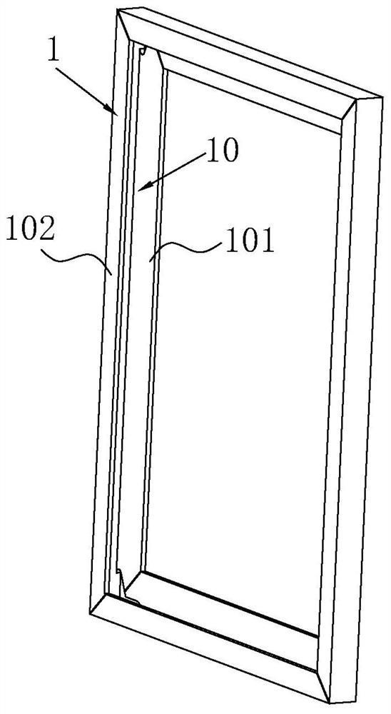
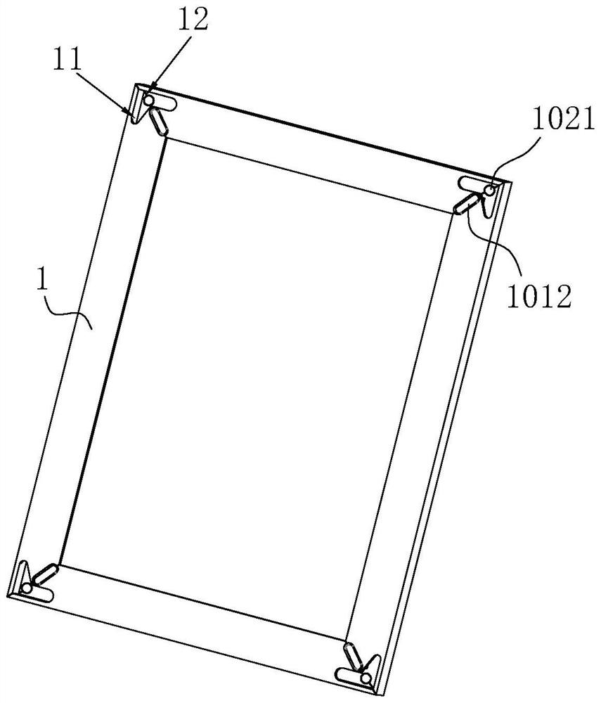
[0044] S1, such as figure 2 As shown, the pass groove 11 is opened on the back layer 101 of the branch frame 1 enclosed as the advertisement frame, and the pass groove 11 is located at the seam of adjacent two frame 1, i.e., is located in the angle of 45 ° angle of the branch frame 1 end portion. The side edge, the pass groove 11 penetrates the back layer 101 from the back layer 101 thickness direction, and after the adjacent two frame 1 is coupled, the two brackets 1 are connected to form a through hole 12.

[0045] like figure 2 As shown in this embodiment of the present invention, the bracket 1 is opened each end, and the through holes 12 formed in the adjacent two frame 1 are respectively formed by the triangular pass groove and the other. The strip pass grooves on the branches 1 are formed. This shape of the through hole can not only provide sufficient space for the wel...

Embodiment 2

[0056] The advertisement welding process disclosed in the present invention includes the following steps:

[0057] S1, such as figure 2 As shown, the pass groove 11 is opened on the back layer 101 of the branch frame 1 enclosed as the advertisement frame, and the pass groove 11 is located at the seam of adjacent two frame 1, i.e., is located in the angle of 45 ° angle of the branch frame 1 end portion. The side edge, the pass groove 11 penetrates the back layer 101 from the back layer 101 thickness direction, and after the adjacent two frame 1 is coupled, the two brackets 1 are connected to form a through hole 12.

[0058] like figure 2 As shown in this embodiment of the present invention, the bracket 1 is opened each end, and the through holes 12 formed in the adjacent two frame 1 are respectively formed by the triangular pass groove and the other. The strip pass grooves on the branches 1 are formed. This shape of the through hole can not only provide sufficient space for the wel...

Embodiment 3

[0069] The advertisement welding process disclosed in the present invention includes the following steps:

[0070] S1, such as figure 2 As shown, the pass groove 11 is opened on the back layer 101 of the branch frame 1 enclosed as the advertisement frame, and the pass groove 11 is located at the seam of adjacent two frame 1, i.e., is located in the angle of 45 ° angle of the branch frame 1 end portion. The side edge, the pass groove 11 penetrates the back layer 101 from the back layer 101 thickness direction, and after the adjacent two frame 1 is coupled, the two brackets 1 are connected to form a through hole 12.

[0071] like figure 2 As shown in this embodiment of the present invention, the bracket 1 is opened each end, and the through holes 12 formed in the adjacent two frame 1 are respectively formed by the triangular pass groove and the other. The strip pass grooves on the branches 1 are formed. This shape of the through hole can not only provide sufficient space for the wel...


PUM


Abstract

The invention relates to the field of advertising frame production, and in particular discloses an advertising frame welding process. The method includes the following steps: S1. Opening a plurality of through grooves at the seam position of the back layer of the support frame of the advertising frame, the through grooves penetrate the back layer from the thickness direction of the back layer, and after the two frames are butted, the through grooves form through holes one by one ; S2, butt two support frames, extend the welding torch into the support frame chamber from the through hole, and weld the surface layers of the two pairs of support frames from the inner wall of the surface layer; S3, repeat S2, and weld the remaining support frames to form an advertising frame; S4, in turn Weld the weld between the back layers of each support frame of the advertising frame. By opening a through slot at the seam position of the back layer of the support frame, the welding torch can penetrate into the chamber and weld the back of the support frame surface layer from the inside of the chamber. Therefore, even if traditional argon arc welding or MIG gas shielded welding is used Welding can be done on the back of the finish to avoid welding scars on the front of the finish.

Description

Technical field [0001] The present invention relates to the field of production and manufacturing of advertising frames, in particular, to a advertising frame welding process. Background technique [0002] The advertising frame is also called the advertising frame, the photo frame, which is used to install advertising paintings and play a promotion. [0003] like figure 1 As shown, the advertisement is typically connected by a plurality of branches 1, and the bifid frame 1 is perpendicular to its axial cross section to "C", so that the frame 1 is two-layer structure, that is, branches 1 including the back layer 101. And the surface layer 102, the bracket 1 is connected to form the advertisement frame, and the slot of the "C" shape is formed to mount the advertisement and the chamber 10 of the panel. [0004] In order to ensure the connection strength of the advertisement frame, the branches and brackets 1 are generally connected by welding, but since the bifiduous frame 1 is two-...

Claims


Application Information

Patent Timeline
Patent Type & Authority Patents(China)
IPC IPC(8): B23K9/16B23K9/173B23K9/235B23K9/32
CPCB23K9/16B23K9/173B23K9/235B23K9/32
Inventor 吴雅清许继方
Owner 上海裕纪金属制品有限公司
Why Eureka
Try Eureka