Electron beam welding method for molybdenum alloy and tungsten alloy

A technology of electron beam welding and welding method, applied in electron beam welding equipment, welding equipment, welding/welding/cutting items, etc., can solve problems such as cracks and pores, achieve fine grain size of weld seam, reduce material stress, improve The effect of weld performance

Active Publication Date: 2017-09-22
BEIJING INST OF CONTROL ENG
View PDF7 Cites 10 Cited by
  • Summary
  • Abstract
  • Description
  • Claims
  • Application Information

AI Technical Summary

Problems solved by technology

[0009] The purpose of the present invention is to provide a method for electron beam welding of molybdenum alloy and tungsten alloy to solve the problems of cracks and pores in the welding seam during the welding process.

Method used


Image

  • Electron beam welding method for molybdenum alloy and tungsten alloy
  • Electron beam welding method for molybdenum alloy and tungsten alloy
  • Electron beam welding method for molybdenum alloy and tungsten alloy

Examples


Embodiment 1

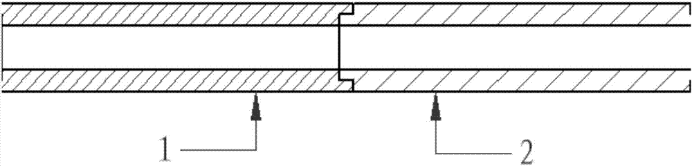
[0063] components to be welded such as figure 2 As shown, the molybdenum alloy component 1 is a hollow cylindrical structure, and the right end surface is provided with a mounting groove. The side end surface is provided with a protrusion matching the installation groove. Molybdenum alloy component 1 is TZM alloy, which is made by powder metallurgy forging method, and tungsten alloy component 2 is WRe25 alloy, which is made by vacuum arc melting method.

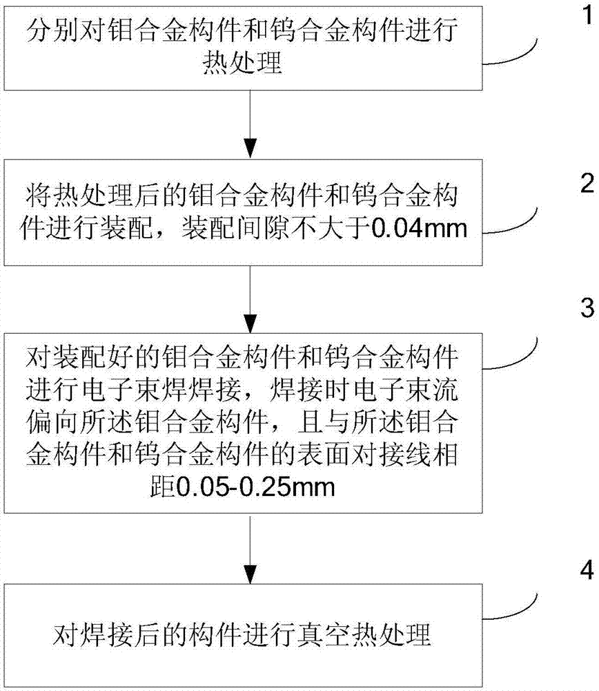
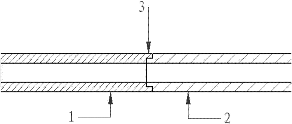
[0064] Electron beam welding is carried out on the molybdenum alloy component 1 and the tungsten alloy component 2, comprising the following steps:

[0065] Step (1): Soak the molybdenum alloy component 1 and the tungsten alloy component 2 in aqua regia for 1 minute, take them out, clean them with alcohol, and then dry them with nitrogen at a pressure of 0.4 MPa;

[0066] Step (2): Put the molybdenum alloy component 1 into a vacuum heating furnace, and the vacuum degree in the furnace is 1X10 -3 Pa, raise the temperature ...

Embodiment 2

[0071] components to be welded such as figure 2 As shown, the molybdenum alloy component 1 is a hollow cylindrical structure, and the right end surface is provided with a mounting groove. The side end surface is provided with a protrusion matching the installation groove. The molybdenum alloy component 1 is a TZC alloy prepared by powder metallurgy followed by forging, and the tungsten alloy component 2 is WRe3 alloy prepared by powder metallurgy followed by forging.

[0072] Electron beam welding is carried out on the molybdenum alloy component 1 and the tungsten alloy component 2, comprising the following steps:

[0073] Step (1): Soak the molybdenum alloy component 1 and the tungsten alloy component in aqua regia for 4 minutes, take them out, wash them with acetone, and then dry them with nitrogen at a pressure of 0.5 MPa;

[0074] Step (2): Put the molybdenum alloy component 1 into a vacuum heating furnace, and the vacuum degree in the furnace is 2X10 -4 Pa, heat up to...

Embodiment 3

[0079] components to be welded such as figure 2 As shown, the molybdenum alloy component 1 is a hollow cylindrical structure, and the right end surface is provided with a mounting groove. The side end surface is provided with a protrusion matching the installation groove. The molybdenum alloy component 1 is a TZC alloy, which is made by vacuum arc melting, and the tungsten alloy component 2 is a WRe3 alloy, which is made by forging after powder metallurgy preparation.

[0080] Electron beam welding is carried out on the molybdenum alloy component 1 and the tungsten alloy component 2, comprising the following steps:

[0081] Step (1): Soak the molybdenum alloy component 1 and the tungsten alloy component in aqua regia for 1 minute, take them out, clean them with alcohol, and then dry them with nitrogen at a pressure of 0.3 MPa;

[0082] Step (2): Put the molybdenum alloy component 1 into a vacuum heating furnace, and the vacuum degree in the furnace is 5X10 -4 Pa, raise the...


PUM

PropertyMeasurementUnit
widthaaaaaaaaaa

Abstract

The invention relates to an electron beam welding method for a molybdenum alloy and a tungsten alloy, and belongs to the technical field of welding processes. The method comprises the following steps of: separately performing thermal treatment on a molybdenum alloy component and a tungsten alloy component, and assembling the molybdenum alloy component and the tungsten alloy component subjected to thermal treatment with an assembly gap not greater than 0.04 mm; performing electron beam welding on the assembled molybdenum alloy component and the assembled tungsten alloy component, deflecting electron beam current to the molybdenum alloy component during welding, and enabling distance between a surface butt-joint line of the molybdenum alloy component and a surface butt-joint line of the tungsten alloy component to be 0.05-0.25 mm; and performing vacuum thermal treatment on the welded components. The welding method provided by the invention is high in cooling speed, is small in welding seam crystalline grain, is relatively small in dimension of a second phase, is beneficial for improving welding seam performances, is good in welding seam surface forming, is relatively high in welding seam internal quality, is high in mechanical property, has welding seam strength greater than 250 MPa, is high in sealing performance, is small in welding seam width and is high in reliability.

Description

technical field [0001] The invention belongs to the technical field of welding technology, and relates to a process method for welding dissimilar refractory materials molybdenum alloy and tungsten alloy by vacuum electron beam welding. Background technique [0002] The welding of refractory materials molybdenum alloy or tungsten alloy mainly adopts argon tungsten arc welding, laser welding, vacuum electron beam welding, diffusion welding and other methods, mainly for welding of the same kind of refractory alloy. [0003] Dissimilar refractory materials molybdenum alloy and tungsten alloy are difficult to weld well due to the following problems: [0004] ①The plastic-brittle transition temperature of molybdenum alloy and tungsten alloy is often higher than the ambient temperature; [0005] ②The initial recrystallization temperature of molybdenum alloy and tungsten alloy is above 1000℃, while the melting point of molybdenum alloy is about 2600℃, and the melting point of tungs...

Claims


Application Information

Patent Timeline
Patent Type & Authority Applications(China)
IPC IPC(8): B23K15/00B23K103/18
Inventor 王文平张志伟申坤赵连清武胜勇王永钢李长维王建王宇
Owner BEIJING INST OF CONTROL ENG
Why Eureka
Try Eureka