Automobile part turning tool

A technology of auto parts and turning, which is applied in the direction of metal processing machinery parts, positioning devices, manufacturing tools, etc. It can solve the problems of not being able to meet the production needs, not being able to automatically tighten the hydraulic rod, and increasing the clamping time, so as to improve product quality and Economic benefits, reliable clamping, and tool cost reduction

Pending Publication Date: 2018-09-28
SHIYAN HEJUN IND
View PDF0 Cites 0 Cited by
  • Summary
  • Abstract
  • Description
  • Claims
  • Application Information

AI Technical Summary

Problems solved by technology

[0002] When turning many metal parts, due to the influence of the part structure, the hydraulic rod of the lathe itself cannot be used for automatic tightening, so workers need to use a wrench to manually lock, which not only increases the clamping time, but also increases the labor intensity of the workers. Under the background of modern labor shortage, this kind of tooling cannot meet the production needs and is not popular among workers.
[0003] Especially for non-circular parts in the clamping part, ordinary tooling cannot achieve symmetrical center of weight and cannot rotate smoothly. The centrifugal force is relatively large during turning, and the workpiece is affected by the centrifugal force, which reduces the concentricity during rotation, so that the lathe can only be rotated at a low Machining at a high speed will not only damage the spindle, but also increase the wear of the tool due to the non-concentric rotation

Method used


Image

  • Automobile part turning tool
  • Automobile part turning tool
  • Automobile part turning tool

Examples


Embodiment Construction

[0014] The present invention will be further described in detail below in conjunction with the accompanying drawings and specific embodiments.

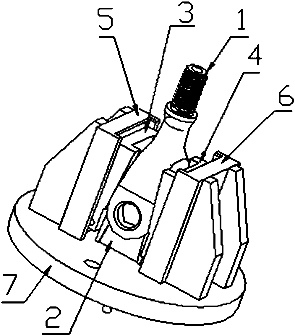
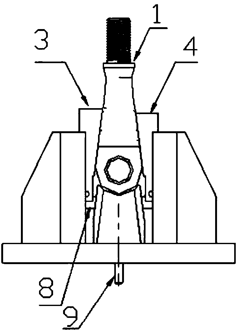
[0015] Such as figure 1 with figure 2 As shown, a turning tool for auto parts, including a central self-aligning diagonal brace 2, a left slider 3, a right slider 4, a left sliding support 5, a right sliding support 6, a flange 7, a slider Support 8, pull rod 9.

[0016] The flange 7 is fixed on the faceplate of the main shaft of the lathe by bolts, the tie rod 9 is connected to the hydraulic pull rod of the lathe by threads, the slider bracket 8 is connected to the head of the tie rod by pins, and the left slider 3 and the right slider 4 are connected by pins. At the two ends of the slider support 8, the center self-aligning diagonal brace 2 is fixed on the center of the flange 7 by screws. The left sliding support block 5 and the right sliding support block 6 are arranged on the outside of the central self-aligning diagonal supp...


PUM


Abstract

The invention discloses an automobile part turning tool. The automobile part turning tool comprises a flange plate bottom plate, left and right slide blocks, a center automatic-aligning inclined supporting block, a slide block bracket, a slide supporting block, a pulling rod, a rotary shaft and a pin, wherein a screw hole is formed in a flange plate to lock with a numerical-control lathe main shaft; a hole for allowing the pulling rod to pass through is formed in the flange plate; the automatic-aligning inclined supporting block and the slide supporting block are fixedly arranged on the flangeplate; the slide block bracket is connected with a pulling rod movable joint; and the two ends of the bracket are connected with the left and right slide blocks through rotary shafts. The product appearance has symmetrical inclined surfaces, so that in the X direction, a product inner cavity has symmetrical inclined surfaces, and in a Y direction, the left and right slide blocks automatically align, position and clamp in the X direction; the center automatic-aligning inclined supporting block is automatically centered, aligned and positioned in the Y direction; and according to the back-off inclined surface in the X direction, a hydraulic pulling rod drives the left and right slide blocks to firmly lock the product on the Y-direction automatic aligning inclined support block through the slide block bracket, so that the automatic clamping purpose is realized.

Description

technical field [0001] The invention relates to an external thread processing device for a frame bracket of an automobile, belonging to the technical field of automobile manufacturing. Background technique [0002] When turning many metal parts, due to the influence of the part structure, the hydraulic rod of the lathe itself cannot be used for automatic tightening, so workers need to use a wrench to manually lock, which not only increases the clamping time, but also increases the labor intensity of the workers. Under the background of modern labor shortage, this kind of tooling cannot meet the production needs and is not popular among workers. [0003] Especially for non-circular parts in the clamping part, ordinary tooling cannot achieve symmetrical center of weight and cannot rotate smoothly. The centrifugal force is relatively large during turning, and the workpiece is affected by the centrifugal force, which reduces the concentricity during rotation, so that the lathe c...

Claims


Application Information

Patent Timeline
Patent Type & Authority Applications(China)
IPC IPC(8): B23Q3/12
CPCB23Q3/12
Inventor 杨东奎
Owner SHIYAN HEJUN IND
Why Eureka
Try Eureka