Supercharge Your Innovation With Domain-Expert AI Agents!

A cutting device for sheet metal

A technology for cutting devices and plates, applied in metal processing equipment, maintenance and safety accessories, metal processing machinery parts, etc., can solve the problems of delaying the normal operation of work and polluting the working environment, and achieve the effect of simple structure

Active Publication Date: 2019-09-24
山东鹤洋木业有限公司
View PDF5 Cites 1 Cited by
  • Summary
  • Abstract
  • Description
  • Claims
  • Application Information

AI Technical Summary

Problems solved by technology

[0002] Machining refers to the process of changing the shape or performance of the workpiece through a mechanical device. According to the difference in processing methods, it can be divided into cutting processing and pressure processing. The existing plate cutting machine, in the process of cutting the plate, will A large amount of waste is generated, which pollutes the working environment. If the waste is not cleaned up in time, it will delay the normal work

Method used


Image

  • A cutting device for sheet metal
  • A cutting device for sheet metal

Examples


Embodiment Construction

[0016] The following will clearly and completely describe the technical solutions in the embodiments of the present invention with reference to the accompanying drawings in the embodiments of the present invention. Obviously, the described embodiments are only some, not all, embodiments of the present invention.

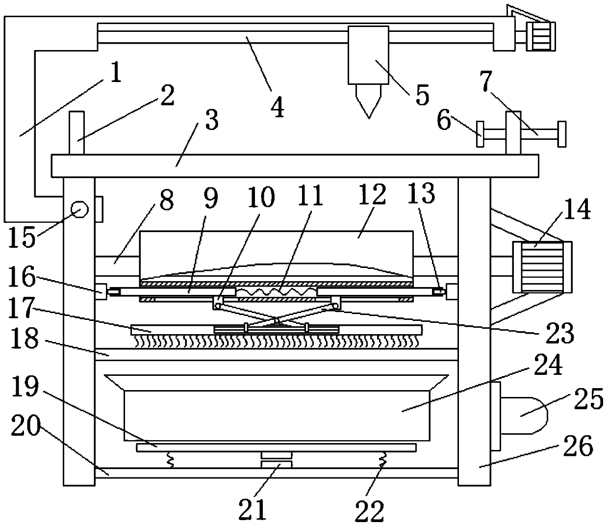
[0017] refer to Figure 1-2 , a cutting device for sheet materials, comprising a grid plate 3, the bottom of the grid plate 3 is symmetrically connected with support plates 26, one side of one of the support plates 26 is provided with a sliding port, and the inner wall of the sliding port is rotatably connected with a second Three screw rods 15, the third screw rod 15 is threadedly connected with the working frame 1, one end of the third screw rod 15 penetrates the inner wall of the slide port and is connected with the output end of the third motor, the shell of the third motor is connected with the supporting plate 26, and the working frame The bottom of the horizon...


PUM


Abstract

The invention discloses a plate cutting device which comprises a grid plate. Support plates are symmetrically connected to the bottom part of the grid plate; a sliding port is formed in one side of one support plate; a third screw rod is rotatably connected to an inner wall of the sliding port; and a working frame is in threaded connection onto the third screw rod. The plate cutting device provided by the invention is simple in structure; a plate is placed on the grid plate, a second screw rod is rotated, and the plate is clamped by utilizing clamping plates, so that cut scraps fall on a firststraight plate; a first motor drives a driving belt to rotate through a rotary shaft, the driving belt drives first straight rods to move together, and when the first straight rods moves to be located in the same horizontal plane with pressing blocks, the two first straight rods move face to face so as to compress a first spring; two second straight rods rotate in a crossing way, and a brush plate is driven to be close to the first straight plate, so that the waste scraps are swept into a refuse hopper; and when the waste scraps in the refuse hopper are accumulated to a certain degree, two conductive blocks contact, a circuit is switched on, and an alarm device gives an alarm, so that people is reminded of transporting the refuse.

Description

technical field [0001] The invention relates to the technical field of mechanical processing, in particular to a cutting device for plates. Background technique [0002] Machining refers to the process of changing the shape or performance of a workpiece through a mechanical device. According to the difference in processing methods, it can be divided into cutting processing and pressure processing. A large amount of waste is produced, which pollutes the working environment. If the waste is not cleaned up in time, it will also delay the normal operation of the work. Contents of the invention [0003] The object of the present invention is to propose a cutting device for plates in order to solve the shortcomings in the prior art. [0004] In order to achieve the above object, the present invention adopts the following technical solutions: [0005] A cutting device for plates, comprising a grid plate, the bottom of the grid plate is symmetrically connected with a support pla...

Claims


Application Information

Patent Timeline
Patent Type & Authority Patents(China)
IPC IPC(8): B23Q11/00
Inventor 陈慎慎
Owner 山东鹤洋木业有限公司
Features
  • R&D
  • Intellectual Property
  • Life Sciences
  • Materials
  • Tech Scout
  • Unparalleled Data Quality
  • Higher Quality Content
  • 60% Fewer Hallucinations
Learn More