
Compression and conveying device for rural garbage treatment

A technology of garbage disposal and conveying device, applied in the directions of transportation and packaging, presses, loading/unloading, etc., can solve the problems of good compression effect, high transmission efficiency, synchronously driving garbage for conveying, etc., to achieve good compression effect and transmission efficiency. high effect

Active Publication Date: 2018-09-28
章雪霞
View PDF9 Cites 15 Cited by
  • Summary
  • Abstract
  • Description
  • Claims
  • Application Information

AI Technical Summary

Problems solved by technology

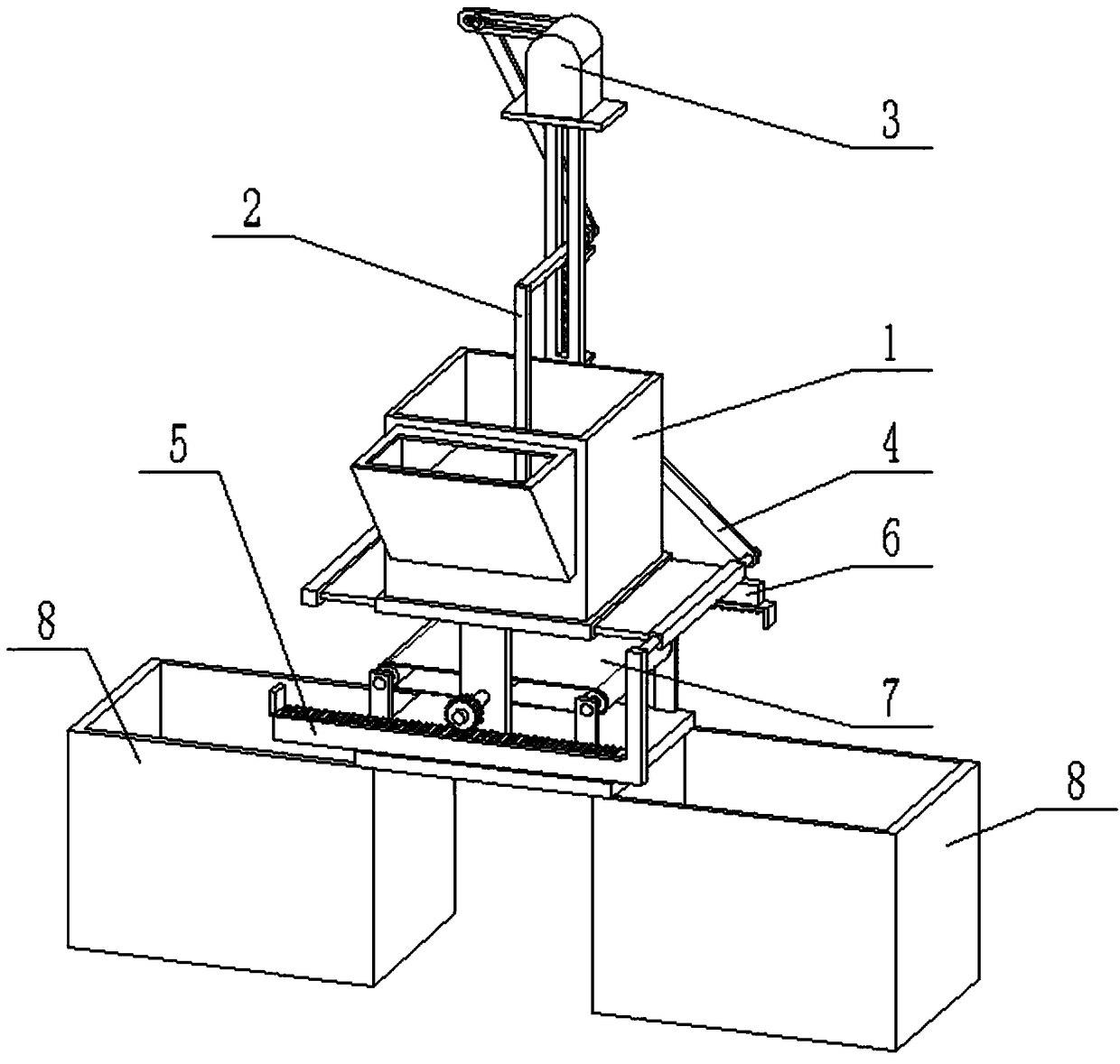
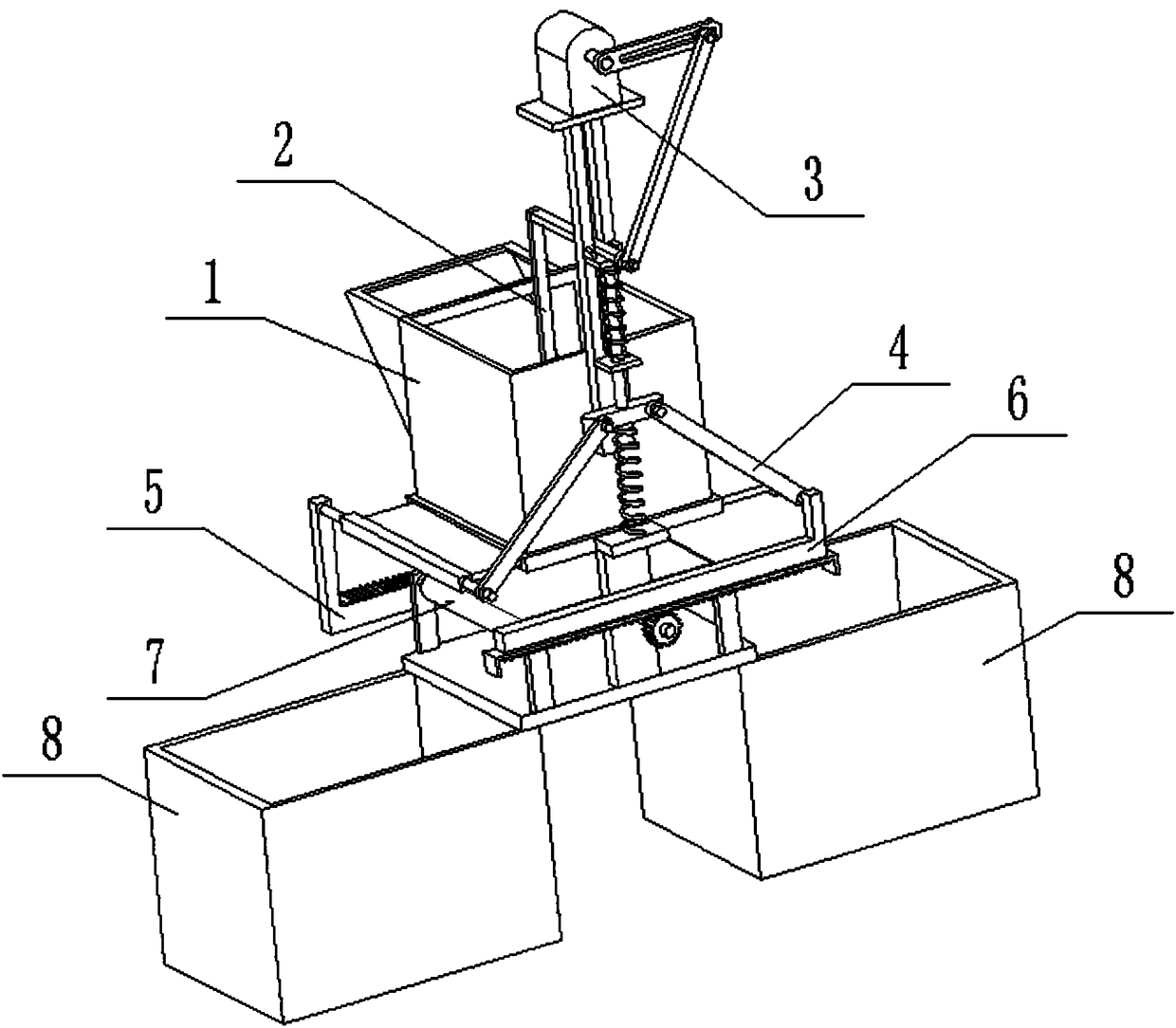
[0003] The purpose of the present invention is to provide a compression conveying device for rural waste treatment, which can effectively solve the problem that the waste treatment device in the prior art cannot synchronously drive the waste to be transported after compressing the waste; the present invention is equipped with a waste compression Components, the garbage compression component can efficiently compress the garbage inside the compression box component. After compression, the garbage compression component drives the door at the lower end of the compression box component to open through the garbage blanking transmission component to realize automatic blanking of the compressed garbage, and then in the When the box door at the lower end of the compression box assembly is closed, the compression box assembly drives the garbage conveyor belt assembly to carry out the conveying work, and transports the compressed garbage to the garbage storage box. The present invention adopts the compression drive assembly for drive control as a whole, with high transmission efficiency and good compression effect

Method used


Image

  • Compression and conveying device for rural garbage treatment
  • Compression and conveying device for rural garbage treatment
  • Compression and conveying device for rural garbage treatment

Examples


specific Embodiment approach 1

[0029] Such as Figure 1-12 As shown, the compression conveying device for rural waste treatment includes a compression box assembly 1, a waste compression assembly 2, a compression drive assembly 3, a waste discharge transmission assembly 4, a front drive rack assembly 5, a rear drive rack assembly 6, and a waste conveying assembly. Belt assembly 7 and two garbage storage boxes 8, the lower end of the compression box assembly 1 is fixedly connected to the garbage conveyor belt assembly 7, and the two sides of the bottom end of the garbage conveyor belt assembly 7 are respectively fixedly connected to a garbage storage box 8; The inside of the compression box assembly 1 is provided with a garbage compression assembly 2, the rear end of the garbage compression assembly 2 is fixedly connected to the rear end of the compression box assembly 1, the compression drive assembly 3 is arranged on the top of the garbage compression assembly 2, and the compression drive assembly 3 is conn...

specific Embodiment approach 2

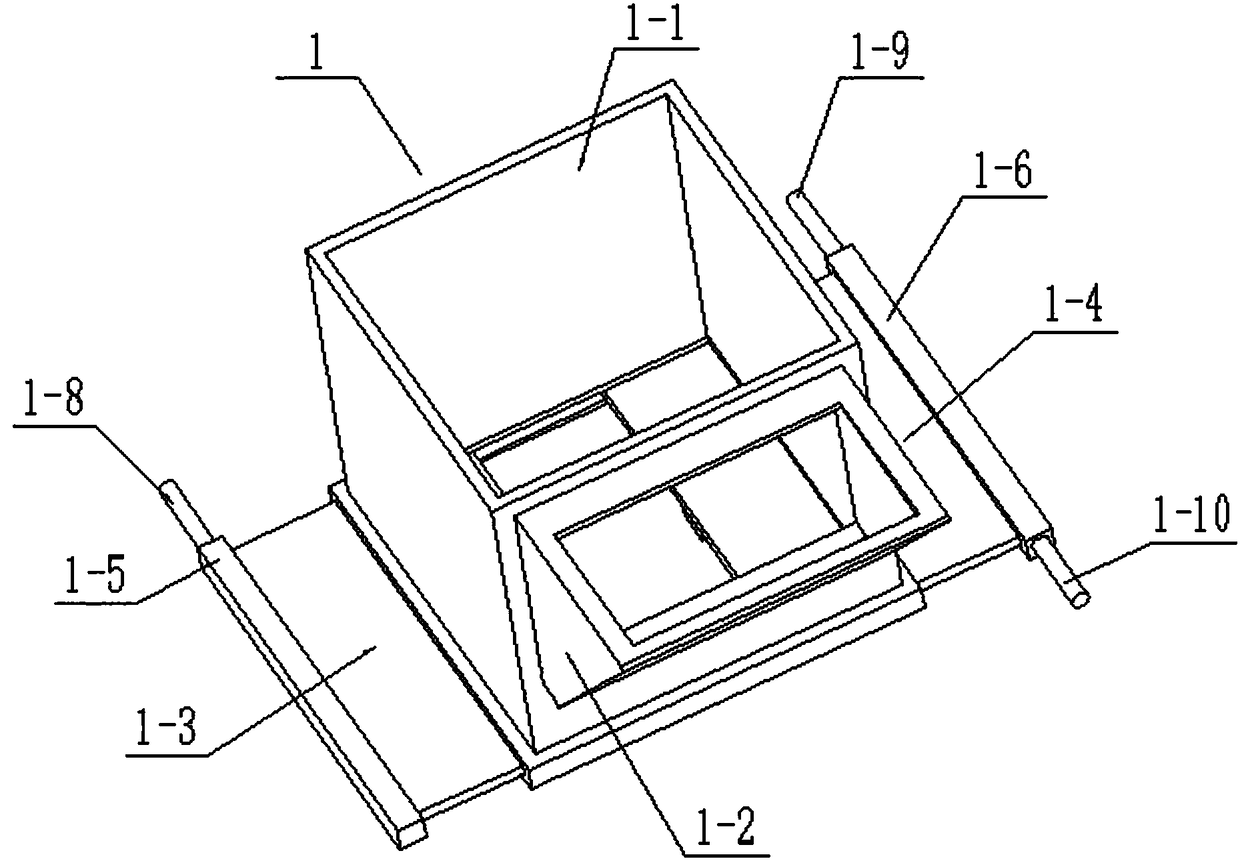
[0030] Such as Figure 1-12 As shown, the compression box assembly 1 includes a rectangular compression box 1-1, a trapezoidal feed hopper 1-2, a left box door 1-3, a right box door 1-4, a left pull rod 1-5, and a right pull rod 1-6 , limit block 1-7, first connecting rod 1-8, second connecting rod 1-9 and third connecting rod 1-10; the top and bottom surfaces of the rectangular compression box 1-1 are hollow structures, The front side of the rectangular compression box 1-1 is provided with a garbage drop opening, and the front end of the garbage drop opening is fixedly connected to the trapezoidal feed hopper 1-2; The lower end of the left side, the right box door 1-4 is slidably connected to the lower end of the right side of the continuation row compression box, the left box door 1-3 and the right box door 1-4 are relatively arranged, and the bottom surface of the left box door 1-3 The right side and the left side of the bottom surface of the right box door 1-4 are respect...

specific Embodiment approach 3

[0035] Such as Figure 1-12 As shown, the front transmission rack assembly 5 includes a front L-shaped connecting plate 5-1, a front rack plate 5-2 and a front limiting plate 5-3, and the vertical plate of the front L-shaped connecting plate 5-1 is fixedly connected On the third connecting rod 1-10; the top surface of the horizontal plate of the front L-shaped connecting plate 5-1 is fixedly connected to the front rack plate 5-2, and the top surface of the front rack plate 5-2 is provided with Rack teeth, the front rack plate 5-2 is connected to the front end of the garbage conveyor belt assembly 7; the left end of the front rack plate 5-2 is fixedly connected to the front limiting plate 5-3. When the front transmission rack assembly 5 is in use, the front L-shaped connecting plate 5-1 moves under the drive of the third connecting rod 1-10, and the front L-shaped connecting plate 5-1 drives the front rack plate 5-2 To move, the front rack plate 5-2 drives the garbage conveyor...


PUM


Abstract

The invention relates to the field of rural garbage treatment, in particular to a compression and conveying device for rural garbage treatment. The device comprises a compression box module, a garbagecompression module, a compression driving module, a garbage blanking transmission module, a front transmission rack module, a back transmission rack module, a garbage conveying belt module and two garbage storage boxes; the lower end of the compression box module is fixedly connected to the garbage conveying belt module; the garbage storage boxes are fixedly connected to the two sides of the bottom end of the garbage conveying belt module; the garbage compression module is arranged in the compression box module; the back end of the garbage compression module is fixedly connected to the back end of the compression box module; the compression driving module is arranged at the top end of the garbage compression module; and the compression driving module is connected with the garbage compression module. The device can effectively solve the problem that a garbage treatment device in the prior cannot synchronously drive conveying of garbage after compression of the garbage.

Description

technical field [0001] The invention relates to the field of rural garbage treatment, in particular to a compression conveying device for rural garbage treatment. Background technique [0002] Many rural domestic wastes have not been effectively disposed of, among which medical wastes and waste wastes and other dangerous wastes are directly discarded, which not only affects the rural ecological environment to a certain extent, but also directly causes certain damage to the production, life and physical and mental health of rural residents. influences. In addition, the harmful components in the garbage can change the nature and structure of the soil, seriously affecting the yield and quality of crops. At the same time, under the strong erosion of rainwater, the organic matter and harmful substances in the garbage will invade the water body, thereby seriously polluting the water body. The stench formed by the rotting garbage will breed mosquitoes and spread diseases, and the...

Claims


Application Information

Patent Timeline
Patent Type & Authority Applications(China)
IPC IPC(8): B30B9/30B30B15/32B65G65/42
CPCB30B9/3003B30B9/3014B65G65/42
Inventor 章雪霞
Owner 章雪霞
Learn More