
A creasing device for corrugated paper

A corrugated paper and indentation technology, which is applied in the field of corrugated paper indentation devices, can solve the problems of affecting the indentation effect, affecting the use, inconvenient installation, etc., and achieves the effects of good indentation effect, convenient replacement and convenient installation.

Active Publication Date: 2019-08-13
汕头市协泰纸品有限公司
View PDF7 Cites 0 Cited by
  • Summary
  • Abstract
  • Description
  • Claims
  • Application Information

AI Technical Summary

Problems solved by technology

[0002] When corrugated boxes are processed, the cardboard needs to be indented. The traditional indentation equipment is restricted by various disadvantages such as large volume and inconvenient installation. The development of the industry is restricted; the more advanced indentation device currently on the market is the application publication number CN105015030A A corrugated box indentation mechanism with adjustable pressure rollers is disclosed, which drives the rotating pressure rollers on the spline shaft to move in the lateral position through the movement of the limit block to adjust the position of the pressure rollers. The indentation device made and used in the public document found that: when the gap between the rotating pinch wheel and the spline shaft is too large, the rotating pinch wheel will vibrate while rotating, which will affect the actual indentation effect; while the rotating pinch wheel and the spline shaft The clearance of the shaft is too tight, it is easy to get stuck when adjusting the position of the rotating pressure roller, which affects the use

Method used


Image

  • A creasing device for corrugated paper
  • A creasing device for corrugated paper
  • A creasing device for corrugated paper

Examples


Embodiment Construction

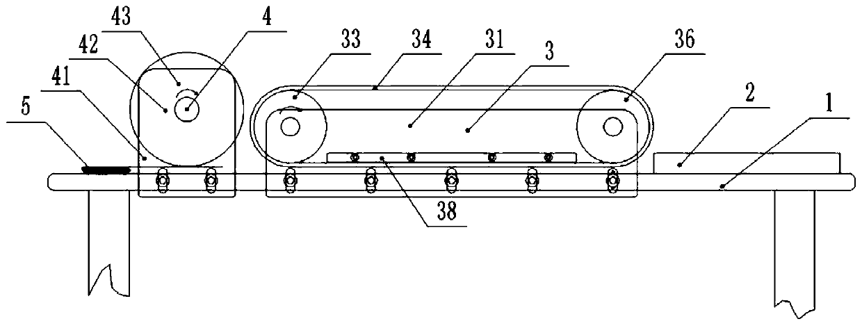
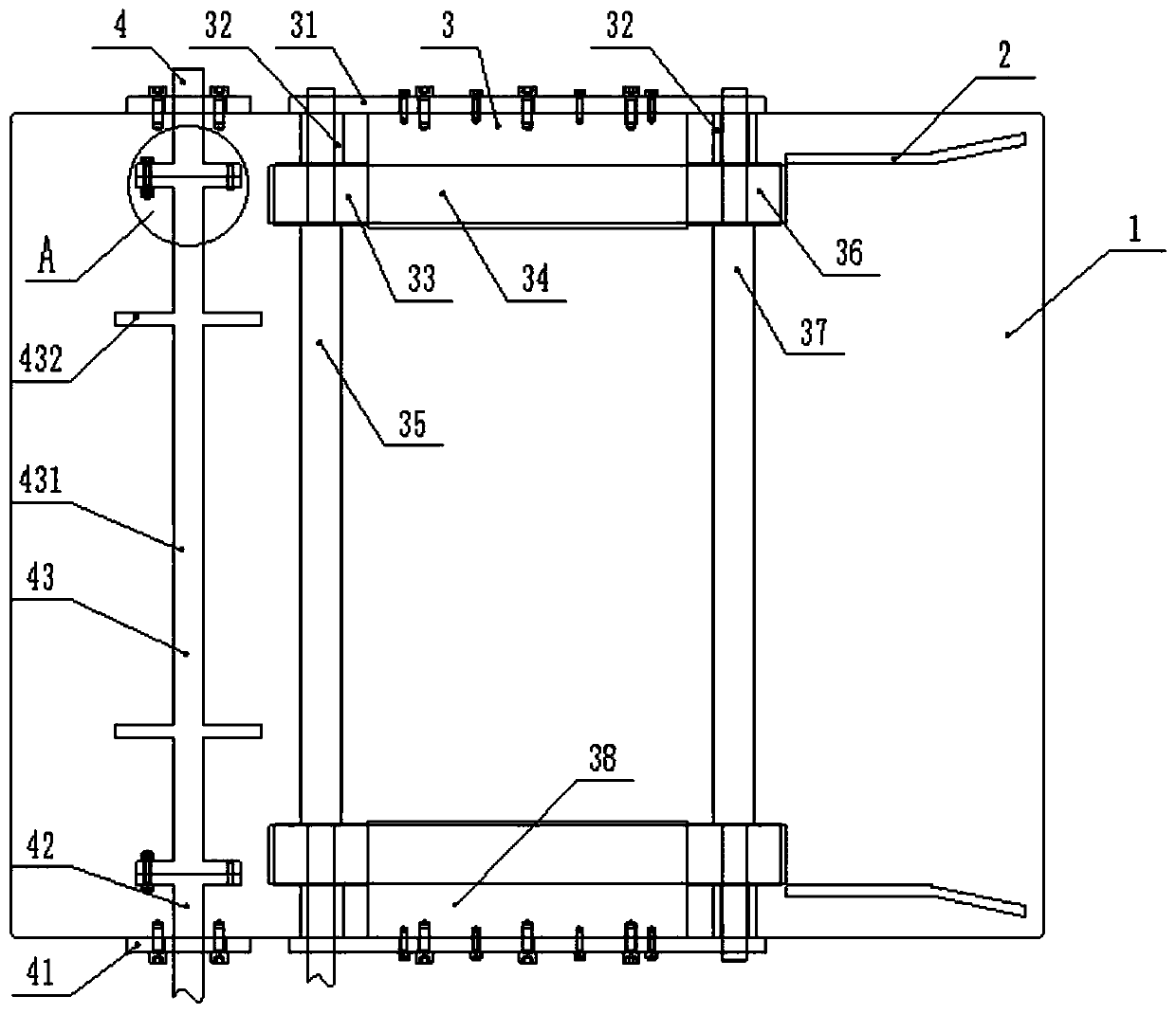
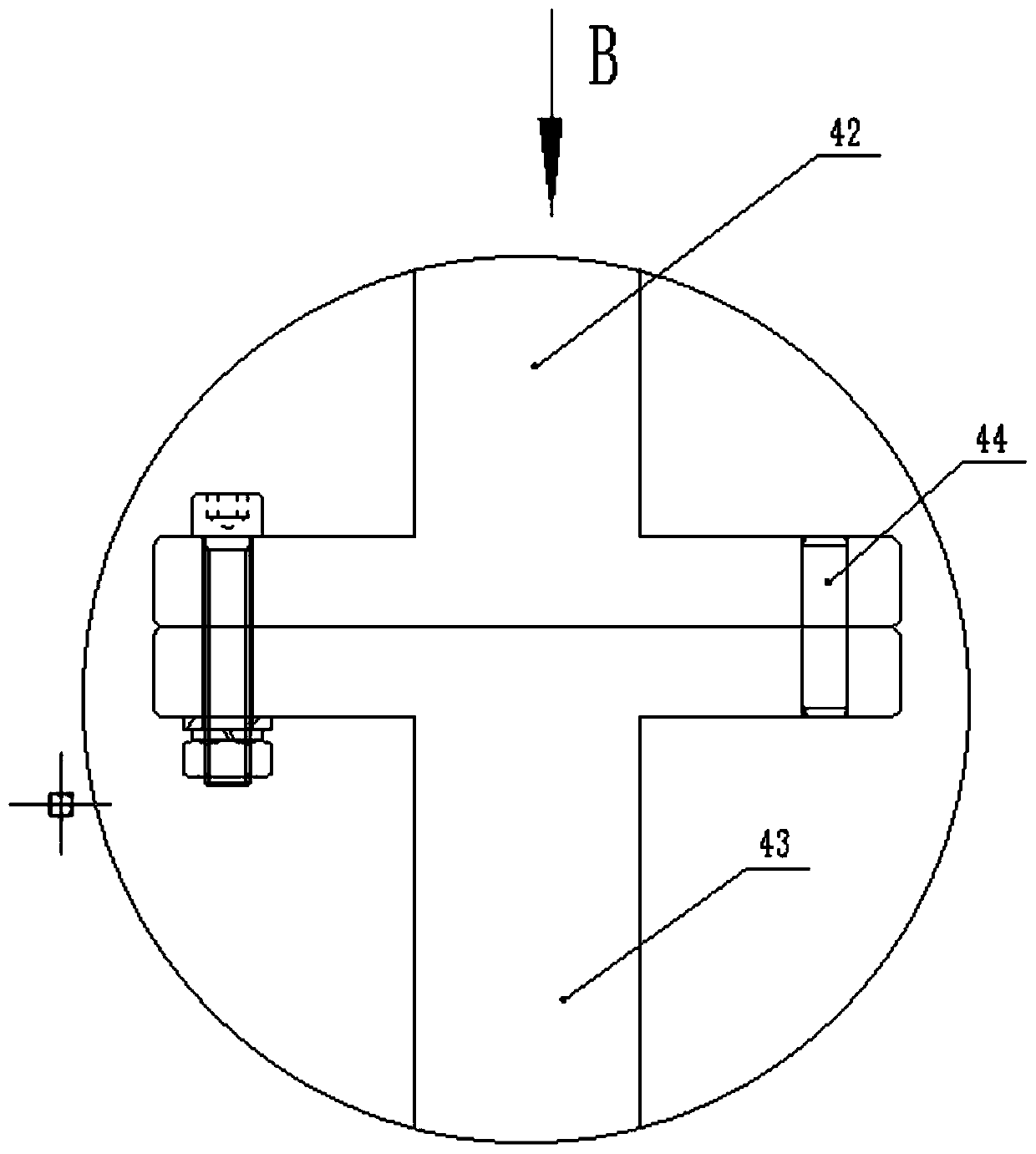
[0026] As shown in the figure, a creasing device for corrugated paper according to the embodiment of the present invention includes: figure 1 As shown, the middle part of the workbench 1 is the conveying mechanism 3, the indentation mechanism 4 is located on the left side of the conveying mechanism 3, and the guide side plate 2 is fixed on the table on the right side of the workbench 1, and the guide side plate 2 is connected with the conveying mechanism 3; Such as figure 1 , figure 2 As shown, the conveying mechanism 3 includes a side plate 31, the height of which is adjustable; The driven shaft 37 is a reducing shaft, the two ends of the driving shaft 35 are equipped with a driving wheel 33, the two ends of the driven shaft 37 are equipped with a driven wheel 36, the driving shaft 35 and the driving wheel 33, the driven shaft 37 and the driven wheel The connection mode of 36 is a spline connection and is equipped with a limit sleeve 32, and the conveyor belt 34 is connect...


PUM


Abstract

The invention discloses a corrugated paper creasing device. The device comprises a workbench, wherein a conveying mechanism is arranged in the middle of the workbench, a creasing mechanism is locatedon the left side of the conveying mechanism, the conveying mechanism comprises a driving shaft and a driven shaft, both the driving shaft and the driven shaft are variable-diameter shafts, the two ends of the driving shaft and the two ends of the driven shaft are provided with driving wheels and driven wheels correspondingly, conveying belts are connected between the driving wheels and the drivenwheels, the creasing mechanism comprises a rolling and pressing shaft, the rolling and pressing shaft is composed of a rolling shaft and pressing wheels, wherein the rolling shaft and the pressing wheels are integrally machined, the two ends of the rolling and pressing shaft are connected with flange connecting pieces, and a guide side plate is located on the right side of the conveying mechanism.According to the corrugated paper creasing device, during use, corrugated paper is fed by a worker from the guide side plate, under the action of the friction force of the conveying belts, the corrugated paper is conveyed to the left, and then creasing of the corrugated paper is completed through the pressing wheels of the creasing mechanism; and the device is simple in mechanism, convenient to install, capable of achieving continuous creasing operation and good in creasing effect.

Description

technical field [0001] The invention relates to the technical field of carton packaging equipment, in particular to a creasing device for corrugated paper. Background technique [0002] When processing corrugated boxes, it needs to indent the cardboard. The traditional indentation equipment is restricted by various disadvantages such as large volume and inconvenient installation. The development of the industry is restricted; the more advanced indentation device currently on the market is the application publication number CN105015030A A corrugated box indentation mechanism with adjustable pressure rollers is disclosed, which drives the rotating pressure roller on the spline shaft to move in the lateral position through the movement of the limit block to adjust the position of the pressure roller. The indentation device made and used in the public document found that: when the gap between the rotating pinch wheel and the spline shaft is too large, the rotating pinch wheel wi...

Claims


Application Information

Patent Timeline
Patent Type & Authority Patents(China)
IPC IPC(8): B31B50/25
CPCB31B50/25
Inventor 龚雅萍
Owner 汕头市协泰纸品有限公司
Learn More