
Mobile charging pile used for new energy automobile

A technology for mobile charging piles and new energy vehicles, applied in electric vehicle charging technology, charging stations, electric vehicles, etc., can solve problems such as difficult maintenance, poor driving skills, limited sockets, etc. The effect of reducing safety accidents

Active Publication Date: 2018-09-28
广西放心源新能源科技有限公司
View PDF9 Cites 7 Cited by
  • Summary
  • Abstract
  • Description
  • Claims
  • Application Information

AI Technical Summary

Problems solved by technology

[0002] At present, most of the new energy vehicle charging piles that are common in cities are fixedly installed on the ground. They charge new energy vehicles through solar power generation or connection to the city's power supply. Generally, they use open lines or dark lines buried in underground pipelines. The lines are easily damaged, and it is difficult to repair the lines with dark lines. Charging piles are public facilities and are generally installed in parking lots or roads. Although they are convenient to use, they are also an obstacle. Some drivers with poor driving skills may not If you don’t pay attention during the process, you will bump into the charging pile, causing traffic accidents, and there are potential safety hazards. Moreover, when the new energy vehicle is charging, the socket is limited, and the driver cannot wait by the side all the time, and does not pull it out in time after it is fully charged , when there are later new energy vehicles that want to charge, they often cannot find the charging port, which brings inconvenience to people's travel

Method used


Image

  • Mobile charging pile used for new energy automobile
  • Mobile charging pile used for new energy automobile
  • Mobile charging pile used for new energy automobile

Examples


Embodiment Construction

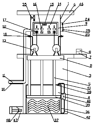
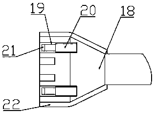
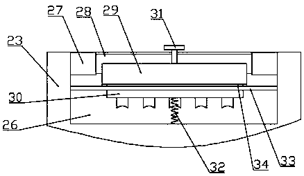
[0021] The present invention is specifically described below in conjunction with accompanying drawing, as Figure 1-5As shown, a mobile charging pile for new energy vehicles includes a charging pile casing 1, the charging pile casing 1 is located on the ground behind the parking space, and the charging pile casing 1 is provided with an up and down movement mechanism, The up and down movement mechanism consists of a fixed base 2 fixedly installed on the lower surface of the charging pile housing 1, a stepped groove 3 located under the ground behind the parking space, and a hydraulic cylinder mechanism 4 fixedly installed on the inner lower surface of the stepped groove 3. , one end of which is inserted into the hydraulic cylinder mechanism 4 and the other end is fixedly connected with the lower surface of the fixed base 2 , a cover 6 fixedly installed on the upper surface of the charging pile shell 1 and corresponding to the size and shape of the stepped groove 3 , fixed The fi...


PUM


Abstract

The invention discloses a mobile charging pile used for a new energy automobile. The mobile charging pile comprises a charging pile shell. An up-down movement mechanism is arranged on the charging pile shell and provided with a fixed base, a stair-shaped groove, a hydraulic cylinder mechanism, lifting columns, a stop cover, a fixing table and a pedal switch. The charging pile shell is provided with a charging mechanism. The charging mechanism is provided with a charging table, a wire inlet channel, a power input lead, charging ports, automatic wire reeling devices, a charging detector, power connection ports, power connection plugs, charging plugs, small round grooves, small electric telescopic rods, damping pads and protection pads. The charging pile shell is provided with a card swipingmechanism. The card swiping mechanism is provided with a card reader, a small display screen, a card containing groove, a square groove, a fixed bearing, a rotary shaft, a rotary board, an input keyboard, a fixed handle, a telescopic spring, a baffle and a rubber pad. A controller is arranged at the upper end in the charging pile shell. The mobile charging pile has the beneficial effects of beingsimple in structure and high in practicability.

Description

technical field [0001] The invention relates to the field of new energy vehicles, in particular to a movable charging pile for new energy vehicles. Background technique [0002] At present, most of the charging piles for new energy vehicles that are common in cities are fixedly installed on the ground. They charge new energy vehicles through solar power generation or connection to urban electricity. Generally, they use open lines or dark lines buried in underground pipelines. The lines are easily damaged, and it is difficult to repair the lines with dark lines. Charging piles are public facilities and are generally installed in parking lots or roads. Although they are convenient to use, they are also an obstacle. Some drivers with poor driving skills may not If you don’t pay attention during the process, you will bump into the charging pile, causing traffic accidents, and there are potential safety hazards. Moreover, when the new energy vehicle is charging, the socket is lim...

Claims


Application Information

Patent Timeline
IPC IPC(8): B60L11/18
CPCB60L53/31Y02T10/70Y02T10/7072Y02T90/12
Inventor 孙小雷
Owner 广西放心源新能源科技有限公司
Learn More