
Air inlet pipe structure for dry air dehumidification and implementation method thereof

An air intake, dry air technology, applied in bridge parts, bridges, buildings, etc., can solve the problems of low dehumidification efficiency and effect of cables, large gas pressure loss, gas pressure loss, etc., and achieve high industrial utilization value and energy saving. Effect

Pending Publication Date: 2018-09-28
FASTEN HONGSHENG GRP CO LTD
View PDF6 Cites 4 Cited by
  • Summary
  • Abstract
  • Description
  • Claims
  • Application Information

AI Technical Summary

Problems solved by technology

However, the application of dry air dehumidification technology for cables of cable-stayed bridges has not been found so far
[0003] For the dry air dehumidification technology of the cable, the invention patent of the authorized announcement number CN103174092A (patent number: ZL201310072105.3) discloses a cable structure that can be filled with dry air and its realization method. The air inlet and outlet stainless steel pipes are respectively installed, and the dry air can be input through the steel pipes to dehumidify the interior of the cable body. Rapid loss of gas pressure, especially for longer and larger cables
Usually, the humidity in the cable body is small in the upper part and higher in the lower part, and when the dry air reaches the lower part of the cable body, the gas pressure loss is very large, which is not conducive to the removal of humidity in the cable body, which leads to low dehumidification efficiency and effect of the cable body

Method used


Image

  • Air inlet pipe structure for dry air dehumidification and implementation method thereof
  • Air inlet pipe structure for dry air dehumidification and implementation method thereof
  • Air inlet pipe structure for dry air dehumidification and implementation method thereof

Examples


Embodiment Construction

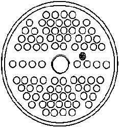
[0027] see Figure 1-3 , the present invention relates to a dry air dehumidification intake pipe structure and its implementation method, which includes the intake pipe 3 body.

[0028] The air inlet pipe 3 is provided with an air outlet 1 at the filling and anchoring surface 5 of the upper anchorage, and the outlet port 2 of the air inlet pipe 3 is close to the position of the filling and anchoring surface 5 of the lower anchorage of the cable body, that is, the upper part of the air inlet pipe 3 is provided with the air outlet 1 by using Part of the dry air in the air inlet pipe 3 dries the upper part of the cable body, while the dry air in the air outlet port 2 of the air inlet pipe 3 dries the part of the cable body near the lower anchorage.

[0029] In the above structure, the length of the cable body is 11m, and the specification is 109×ø5. The air inlet pipe 3 is made of stainless steel pipe, the surface of which is the same as the galvanized aluminum alloy coating of ...


PUM


Abstract

The invention discloses an air inlet pipe structure for dry air dehumidification and an implementation method thereof. A plurality of air outlets are formed in the pouring-anchorage face of an upper anchorage device on a pulling cable, and an air outlet port of the air inlet pipe extends to close to the pouring-anchorage face of a lower anchorage device on the pulling cable. In this way, the dry air dehumidification effect of the pulling cable, especially a long pulling cable is effectively improved. The defect of the pulling cable dry air dehumidification system is effectively overcome; the pulling cable dehumidification efficiency is improved; air inlet pressure is reduced; energy source is saved; and the industrial utility value is achieved.

Description

technical field [0001] The invention relates to the technical field of bridge engineering, in particular to a dry air dehumidification intake pipe structure for bridge cables and a realization method thereof. Background technique [0002] Cable-stayed bridge is one of the important forms of design and application of modern long-span cable-carried bridge structure, and the cable is the core component of the structure, and its load-bearing and load-transmitting capacity is the key to the safe operation of the bridge. High-strength steel wire is the main body of the cable, and its performance is often degraded until failure due to its corrosion during the load-bearing process. Dry air dehumidification technology is to input dry air into the main cable of the suspension bridge through the Roots blower to reduce the humidity in the main cable and effectively prevent the corrosion of the main cable steel wire. It has been successfully used in the humidity control of the main cable...

Claims


Application Information

Patent Timeline
Patent Type & Authority Applications(China)
IPC IPC(8): E01D19/16
CPCE01D19/16
Inventor 郑锐刘礼华陈政清周祝兵赵军宁世伟薛花娟夏涛
Owner FASTEN HONGSHENG GRP CO LTD
Learn More