
Intelligent control system for clean room

An intelligent control system and clean room technology, applied in the field of electronic clean rooms, can solve problems such as energy waste and uneven air intake, and achieve the effect of eliminating turbulence, solving turbulence and uneven air intake, and avoiding energy waste.

Inactive Publication Date: 2018-09-28
SHENZHEN LAUN CLEAN TECH CO LTD
View PDF6 Cites 4 Cited by
  • Summary
  • Abstract
  • Description
  • Claims
  • Application Information

AI Technical Summary

Problems solved by technology

Although the above technical solution can alleviate the problem of uneven air supply, a large amount of fresh air and circulating air will appear turbulent when it is discharged from the air supply pipeline, so the fresh air and circulating air will flow through the air inlet near the air supply pipeline, resulting in 2. Use multiple air supply devices to transmit the fresh air and circulating air in the air supply pipeline to different air inlets. Although this method can completely solve the problem of uniform air intake, in order to ensure that each clean room If all the parameters are maintained within the normal range, all equipment in the clean room must be in a state of non-shutdown for 24 hours. Multiple air supply devices, working all the time will lead to waste of energy

Method used


Image

  • Intelligent control system for clean room
  • Intelligent control system for clean room
  • Intelligent control system for clean room

Examples


Embodiment Construction

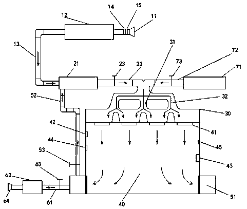
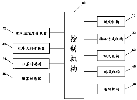
[0019] Below in conjunction with specific embodiment and accompanying drawing, the present invention is further elaborated and illustrated: please refer to figure 1 , an intelligent control system for a clean room, comprising a fresh air mechanism 10, a circulating air supply mechanism 20, a bifurcated air intake pipeline 30, a clean room body 40, a return air mechanism 50, an exhaust mechanism 60, a fire protection mechanism 70 and a control system Institution80.

[0020] The fresh air mechanism 10, the circulating air supply mechanism 20, the bifurcated air inlet pipeline 30, the clean room body 40, the return air mechanism 50 and the exhaust air mechanism 60 are connected in sequence. The circulating air supply mechanism 20 includes an air supply pipeline 22 , and a bifurcated air inlet pipeline 30 is arranged between the air supply pipeline 22 and the clean room body 40 . The bifurcated air inlet pipeline 40 includes multi-layer bifurcated branches, each layer is provided...


PUM


Abstract

The invention discloses an intelligent control system for a clean room. The intelligent control system comprises a fresh air mechanism, a circulating air supply mechanism, a clean room chamber body, areturn air mechanism and an exhaust air mechanism which are sequentially connected, wherein the circulating air supply mechanism comprises an air supply pipeline, a bifurcated air inlet pipeline is arranged between the air supply pipeline and the clean room chamber body, the bifurcated air inlet pipeline comprises a plurality layers of bifurcated branches, each layer of the bifurcated branches isprovided with a plurality of branches, each branch is provided with a plurality of sub-branches, a plurality of air inlets are formed in the top of the clean room chamber body, and the air inlets correspond to the sub-branches one by one. The intelligent control system has uniform air intake and energy conservation.

Description

technical field [0001] The invention relates to the technical field of electronic clean rooms, in particular to an intelligent control system for clean rooms. Background technique [0002] With the continuous development of the production process of semiconductor electronic products, more precision and higher integration are the development trend of the industry. The manufacturing process has entered the nanometer era, and the precision requirements for production equipment are becoming more and more stringent. Therefore, in addition to the technological level of the equipment itself needing to meet the production requirements, the production environment in which it is located—the various indicators of the clean room must also be checked. Strictly controlled. [0003] At present, the air supply structure of the clean room is divided into two types: 1. The structure of connecting the air supply pipeline to the air inlet chamber is used to slow down the speed of fresh air and...

Claims


Application Information

Patent Timeline
IPC IPC(8): F24F7/08F24F11/89F24F11/77F24F110/10F24F110/20F24F110/50
CPCF24F7/08F24F11/77F24F11/89F24F2110/10F24F2110/20F24F2110/50Y02B30/70
Inventor 廖志铭
Owner SHENZHEN LAUN CLEAN TECH CO LTD
Features
  • Generate Ideas
  • Intellectual Property
  • Life Sciences
  • Materials
  • Tech Scout
  • Unparalleled Data Quality
  • Higher Quality Content
  • 60% Fewer Hallucinations
Learn More