Supercharge Your Innovation With Domain-Expert AI Agents!

Waste heat reutilization device

A waste heat and hot gas technology, applied in the field of tunnel furnaces, can solve problems such as heat loss

Pending Publication Date: 2018-09-28
GUANGZHOU BAKE OVEN MACHINERY
View PDF5 Cites 0 Cited by
  • Summary
  • Abstract
  • Description
  • Claims
  • Application Information

AI Technical Summary

Problems solved by technology

[0004] In order to overcome the deficiencies of the prior art, one of the purposes of the present invention is to provide a waste heat recycling device, which can solve the problem of heat loss

Method used

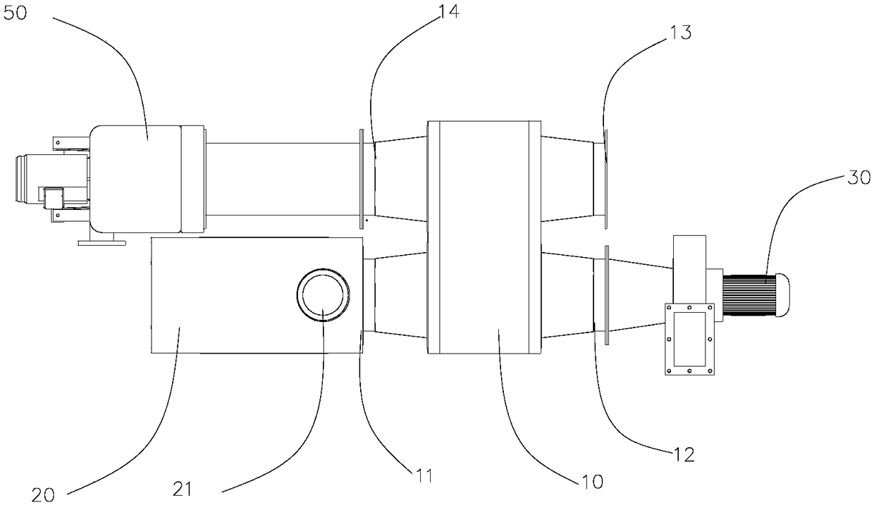
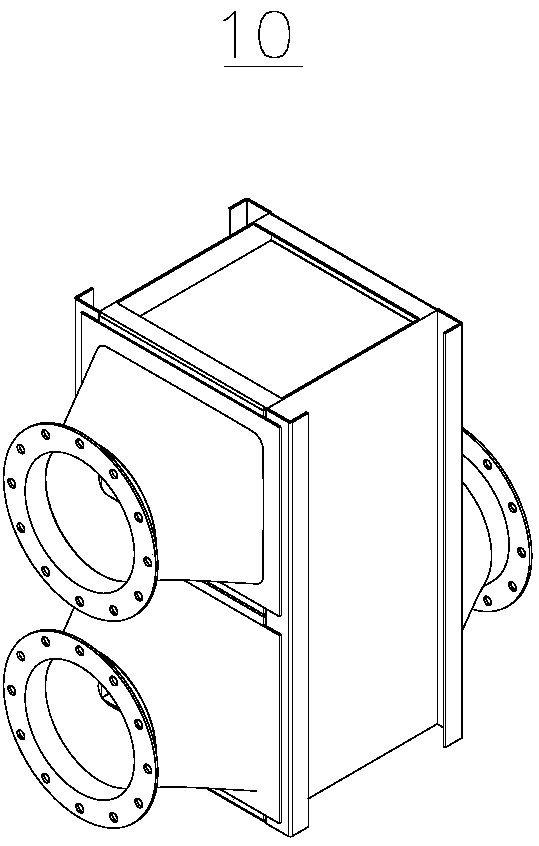
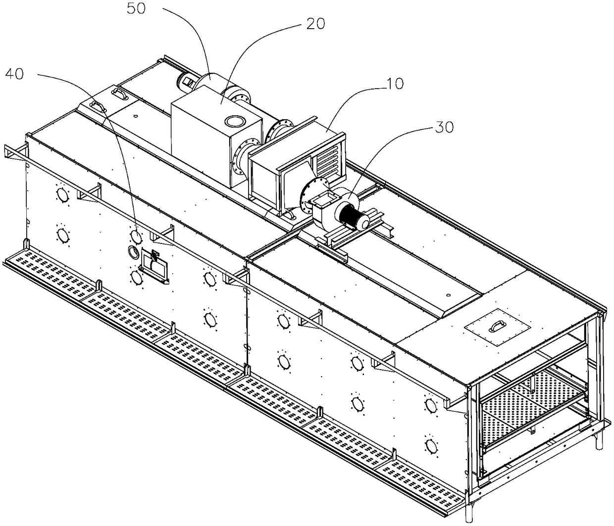

Image

  • Waste heat reutilization device
  • Waste heat reutilization device
  • Waste heat reutilization device

Examples


Embodiment Construction

[0022] Below, the present invention will be further described in conjunction with the accompanying drawings and specific implementation methods. It should be noted that, under the premise of not conflicting, the various embodiments described below or the technical features can be combined arbitrarily to form new embodiments. .

[0023] It should be noted that when a component is said to be "fixed" to another component, it can be directly on the other component or there can also be an intervening component. When a component is said to be "connected" to another component, it may be directly connected to the other component or there may be intervening components at the same time. When a component is said to be "set on" another component, it may be set directly on the other component or there may be an intervening component at the same time. The terms "vertical," "horizontal," "left," "right," and similar expressions are used herein for purposes of illustration only.

[0024] Un...


PUM


Abstract

The invention discloses a waste heat reutilization device which comprises a hot gas conveying pipeline, an exhaust unit and a heat exchange unit; one end of the hot gas conveying pipeline is connectedwith the interior of a tunnel furnace; the heat exchange unit is internally provided with a transfer medium, a first heat exchange channel and a second heat exchange channel; the first heat exchangechannel is provided with an access hole and a discharge hole which are communicated with the hot gas conveying pipeline and the exhaust unit respectively, the hot gas conveying pipeline conveys wet flue gas after combustion of the tunnel furnace to the first heat exchange channel for heat exchange, the wet flue gas after heat exchange is exhausted by the exhaust unit, and heat is transferred to the transfer medium; and the second heat exchange channel is provided with an access hole and a discharge hole and accesses a heating medium, the wet flue gas is exhausted by the discharge hole of the second heat exchange channel after being heated with the transfer medium. When the heating medium is air, the heated air enters a combustion system in the tunnel furnace through an air system for combustion supporting, and heat is recycled; and when the heating medium is water, the heated water can be used for an external hot water used end.

Description

technical field [0001] The invention relates to the technical field of tunnel furnaces, in particular to a waste heat recycling device. Background technique [0002] As the demand of consumers increases, the output of food tunnel furnaces increases, and the consumption of gas and electricity is also increasing. Domestic tunnel furnace equipment started late in terms of energy saving and emission reduction, and is still groping forward. [0003] The energy consumption of food tunnel furnaces is closely related to gas combustion efficiency, heat loss, exhaust gas emissions and other links. In order to control the moisture requirements of food, domestic tunnel furnaces still use the method of pumping hot gas and moisture together. Since water vapor and hot air are mixed, the high-temperature gas carries a lot of heat during the discharge process, resulting in waste of heat. Therefore, in the food tunnel furnace industry, there is an urgent need for a kind of equipment that ca...

Claims


Application Information

Patent Timeline
Patent Type & Authority Applications(China)
IPC IPC(8): F27D17/00F27B9/36
CPCF27B9/36F27D17/004Y02P10/25
Inventor 邵鸿飞侯杲杲
Owner GUANGZHOU BAKE OVEN MACHINERY
Features
  • R&D
  • Intellectual Property
  • Life Sciences
  • Materials
  • Tech Scout
  • Unparalleled Data Quality
  • Higher Quality Content
  • 60% Fewer Hallucinations
Learn More