Fabric sensor for pressure distribution monitoring

A distributed monitoring and fabric sensor technology, applied in the field of fabric sensors, can solve problems such as increasing the manufacturing process, misalignment of upper and lower electrodes, and inability to conduct electrodes, etc., and achieve the effects of less manufacturing process, less damage, and improved accuracy

Pending Publication Date: 2018-09-28
上海思澄智能科技有限公司
View PDF6 Cites 12 Cited by
  • Summary
  • Abstract
  • Description
  • Claims
  • Application Information

AI Technical Summary

Problems solved by technology

Because the upper and lower layers are a non-integral structure (stacked), when the pressure deformation of each layer structure is greatly different, it is easy to cause the upper and lower electrodes to be misaligned, resulting in local upper and lower electrodes that may not be able to conduct, especially when the pressure and sensor area are large This phenomenon is especially evident when
At the same time, this also increases the manufacturing process, and the production cost is high.

Method used


Image

  • Fabric sensor for pressure distribution monitoring
  • Fabric sensor for pressure distribution monitoring
  • Fabric sensor for pressure distribution monitoring

Examples


Embodiment

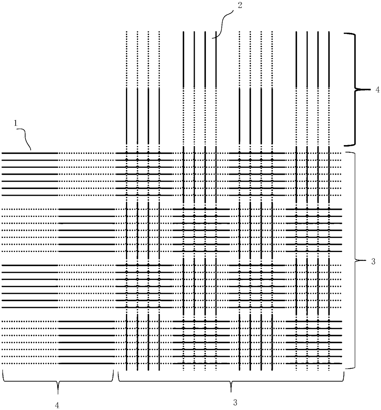
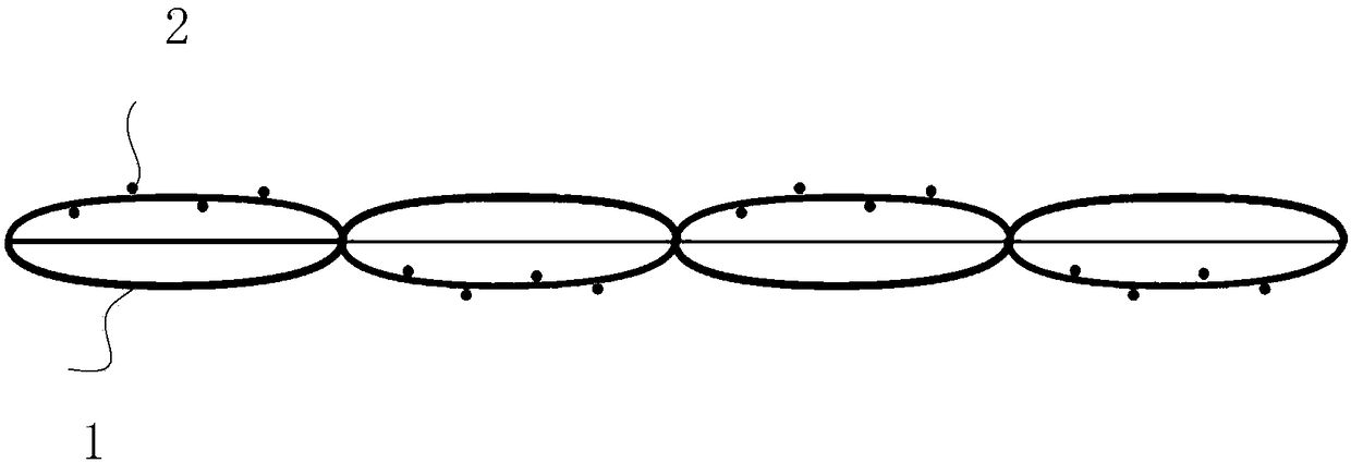
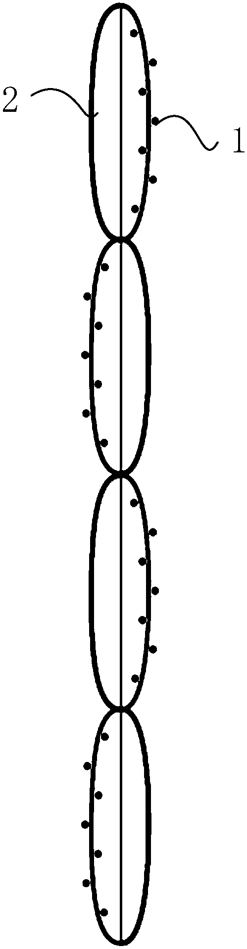
[0032] like figure 1 , figure 2 and image 3 As shown, a fabric sensor for pressure distribution monitoring includes warp yarns 2 and weft yarns 1, the warp yarns 2 and weft yarns 1 are intersected and arranged, and the intersecting warp yarns 2 and weft yarns 1 constitute a sensing area 3 and a connecting area 4, The connection area 4 is positioned at the side of the induction area 3, and the head end of each row of warp yarns 2 in the connection area 4 is connected to the power supply end, and the head end of each row of weft yarns 1 in the connection area 4 is connected to the collection end. Area 3 is composed of staggered sensing units, and each sensing unit is arranged in a sandwich structure, wherein the upper layer and the lower layer are the positive electrode layer and the base layer respectively, and the middle layer is a conductive layer, and the positive electrode layer and the negative electrode layer are composed of several conductive layers. yarn and non-con...

Embodiment 1

[0035] On the basis of the above-mentioned embodiments, as Figure 4 As shown, make it into 16*16 (row*column) samples for corresponding point pressure test. In the present invention, 70D silver-plated conductive yarn is used as the conductive weft yarn and conductive warp yarn in the upper and lower layers, and the twisted resistance yarn synthesized by 150D bright polyester yarn core and 20D nylon carbon black conductive yarn (winding yarn) is used as the middle layer resistance yarn , 70D polyester filament is used as the non-conductive warp yarn in each layer, and 150D polyester filament is used as the non-conductive weft yarn in each layer.

[0036] like Figure 5 Shown, adopt embodiment to combine the structure of embodiment again, to Figure 4 The point A on the sample surface in is subjected to press sampling, as shown in Table 1:

[0037] Table 1:

[0038]

[0039]

[0040] like Image 6 shown, yes Figure 4 Point B of the sample surface in the sample is s...


PUM


Abstract

The invention relates to a fabric sensor for pressure distribution monitoring. The fabric sensor comprises warp yarns and weft yarns. The warp yarns and the weft yarns are arranged in an orthogonal manner. The crossed warp yarns and weft yarns together form an induction area and a connection area. The head end of each row of the warp yarns in the connection area is connected to a power supply end,and the head end of each row of the weft yarns in the connection area is connected to a collecting end. The induction area is formed by induction units which are arranged in a staggered mode. Each induction unit is arranged in a sandwich-shaped structure, wherein the upper layer and the lower layer of the induction unit are respectively in the form of a positive electrode layer and a negative electrode layer, and the middle layer of the induction unit is in the form of a conductive layer. The positive electrode layer and the negative electrode layer of each induction unit are both composed ofa plurality of conductive yarns and non-conductive yarns. The conductive yarns of the positive electrode layer and the conductive yarns of the negative electrode layer are not adjacent to each other.The conductive yarns of the positive electrode layer and the conductive yarns of the negative electrode layer are orthogonally arranged. The conductive layer is composed of resistance yarns and non-conductive yarns. According to the invention, a positive electrode can be conducted with a negative electrode through the conductive layer with the presence of a compressed and large-area sensor. Therefore, the monitoring accuracy is ensured.

Description

technical field [0001] The invention relates to a fabric sensor, in particular to a fabric sensor for pressure distribution monitoring. Background technique [0002] Pressure sore is one of the most serious clinical nursing deficiencies. Once a pressure sore occurs, it will not only bring pain to the patient, aggravate the condition, prolong the recovery time of the disease, and even endanger life due to sepsis caused by secondary infection in severe cases. Preventive care for pressure ulcers is very important. [0003] The most important cause of pressure sores is that local tissues are under continuous vertical pressure. Therefore, real-time monitoring of pressure magnitude and distribution can help medical staff understand the pressure on local body tissues of patients in various postures in real time, so as to take corresponding nursing measures to help Patients reduce stress, ease pain, reduce the chance of exacerbation of the disease, and shorten the recovery time of ...

Claims


Application Information

Patent Timeline
Patent Type & Authority Applications(China)
IPC IPC(8): G01L1/22D03D1/00D03D15/00D03D15/275D03D15/283D03D15/47D03D15/533
CPCG01L1/22D03D1/0088D03D15/00D10B2331/04D10B2331/02
Inventor 李鹏龙海如卜佳仙潘亮李耿蔚张钰晶
Owner 上海思澄智能科技有限公司
Why Eureka
Try Eureka