Test equipment

A technology of testing equipment and detectors, which is applied in the direction of fluid tightness testing, machine/structural component testing, measuring devices, etc. It can solve problems such as high error rate and air leakage, reduce unreliable sealing and improve detection The effect of accuracy

Pending Publication Date: 2018-09-28
SHANGHAI JINGZHI IND CO LTD
View PDF0 Cites 4 Cited by
  • Summary
  • Abstract
  • Description
  • Claims
  • Application Information

AI Technical Summary

Problems solved by technology

[0004] This test method may cause air leakage due to improper clamping method or air leakage of the clamping device, resulting in a high detection error rate.

Method used


Image

  • Test equipment
  • Test equipment
  • Test equipment

Examples


Embodiment Construction

[0036] The technical solutions of the present invention will be clearly and completely described below in conjunction with the accompanying drawings. Apparently, the described embodiments are some of the embodiments of the present invention, but not all of them. Based on the embodiments of the present invention, all other embodiments obtained by persons of ordinary skill in the art without making creative efforts belong to the protection scope of the present invention.

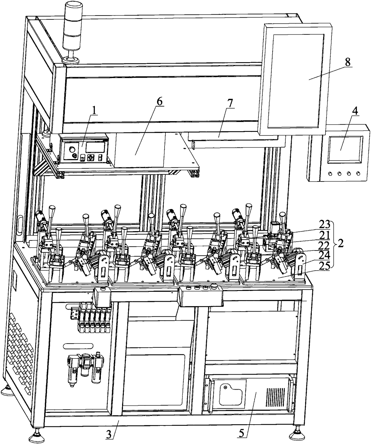
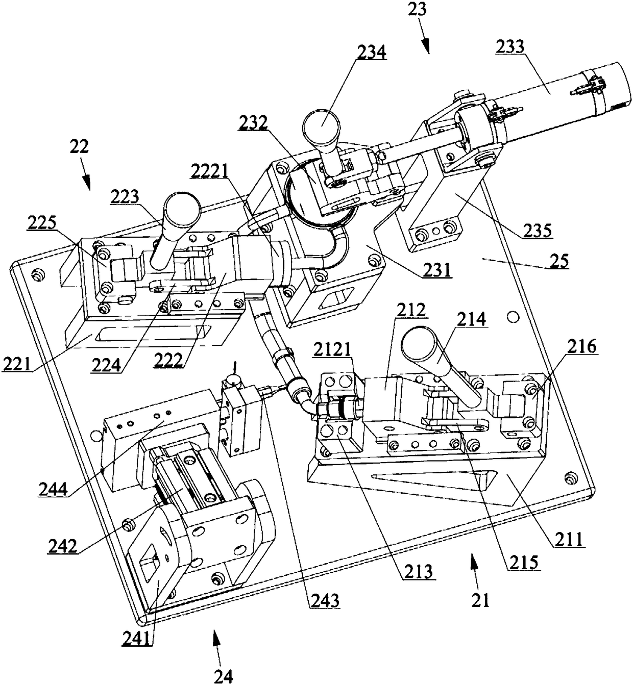
[0037] Such as figure 2 and image 3 As shown, this embodiment discloses a test device, which includes a tester 1, a fixed tool 2, an on-off device, a frame 3, a touch screen 4, a control component, an industrial computer 5, a printing mechanism 6, a display 7, and a production capacity display 8.

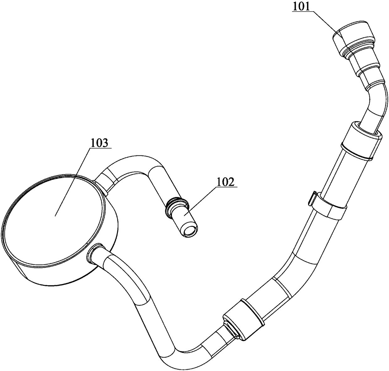
[0038] The fixing tool 2 includes a first blocking device 21 , a second blocking device 22 , a fixing device 23 and a marking device 24 . The first blocking device 21 is in sealing connection with the oil outle...


PUM


Abstract

The invention relates to the technical field of pipeline leakage test, and discloses test equipment, comprising a detector, a fixing tooling and an on-off device. The fixing tool comprises a first plugging device, a second plugging device and a fixing device, wherein the first plugging device is provided with an exhaust passage and is hermetically connected with an oil outlet end of an oil pipe, an air inlet of the exhaust passage is communicated with the oil outlet end; the second plugging device is provided with an air feeding passage connected with an air outlet of the detector, and is hermetically connected with an oil inlet end of the oil pipe, and an air outlet of the air feeding passage is communicated with the oil outlet end; the fixing device can fix the oil pipe. The on-off device is connected with an air outlet of the exhaust passage. Whether a check valve in the oil pipe is on or off or leakage rate of the oil pipe is tested by controlling the on-off device. The oil pipe isfixed and then subjected to hermetical connection, so that air leakage due to poor sealing effect when the oil pipe is moved accidentally can be reduced and test accuracy can be improved.

Description

technical field [0001] The invention relates to the technical field of pipeline leakage testing, in particular to a testing device. Background technique [0002] As we all know, the oil pipes on the car work in a high-pressure environment. In order to ensure that the oil pipes do not leak oil, the pass rate of these pipes is extremely high, and all pipes must be tested for leaks. [0003] Such as figure 1 As shown in the oil pipe, an oil drum 103 is arranged on the oil pipe, and a check valve is installed in the oil pipe to prevent the oil from flowing backward. The oil outlet end 101 of the oil pipe is provided with a sealing gasket, which facilitates the sealing connection with the oil outlet of the oil tank. The upper ring of the oil inlet end 102 is provided with a protrusion, and the oil inlet end 102 stretches into the oil inlet of the machine, and a sealing ring is arranged between the oil inlet and the protrusion, and then fixed by a nut. In the past, the leakage ...

Claims


Application Information

Patent Timeline
Patent Type & Authority Applications(China)
IPC IPC(8): G01M3/28
CPCG01M3/2815
Inventor 刘相辉于子龙胡玉鹏周同沈国双
Owner SHANGHAI JINGZHI IND CO LTD
Why Eureka
Try Eureka