Electric equipment radiating frame

A technology for power equipment and heat dissipation racks, applied in the field of heat dissipation racks, can solve the problems of small space in electric cabinets, reduce work efficiency, and inconvenient installation, and achieve the effects of improving heat dissipation efficiency, improving installation efficiency, and easy operation

Inactive Publication Date: 2018-09-28
陈为志
View PDF0 Cites 0 Cited by
  • Summary
  • Abstract
  • Description
  • Claims
  • Application Information

AI Technical Summary

Problems solved by technology

[0003] During the working process of the transformer, a large amount of heat will be generated inside. If the transformer is not dissipated, it will easily ignite spontaneously and cause a fire. The installation of the power equipment rack in the prior art is inconvenient. Due to the small space of the electric cabinet, the work efficiency is reduced. To this end, we propose a cooling rack for power equipment

Method used


Image

  • Electric equipment radiating frame
  • Electric equipment radiating frame

Examples


Embodiment Construction

[0019] In order to make the technical means, creative features, goals and effects achieved by the present invention easy to understand, the present invention will be further described below in conjunction with specific embodiments.

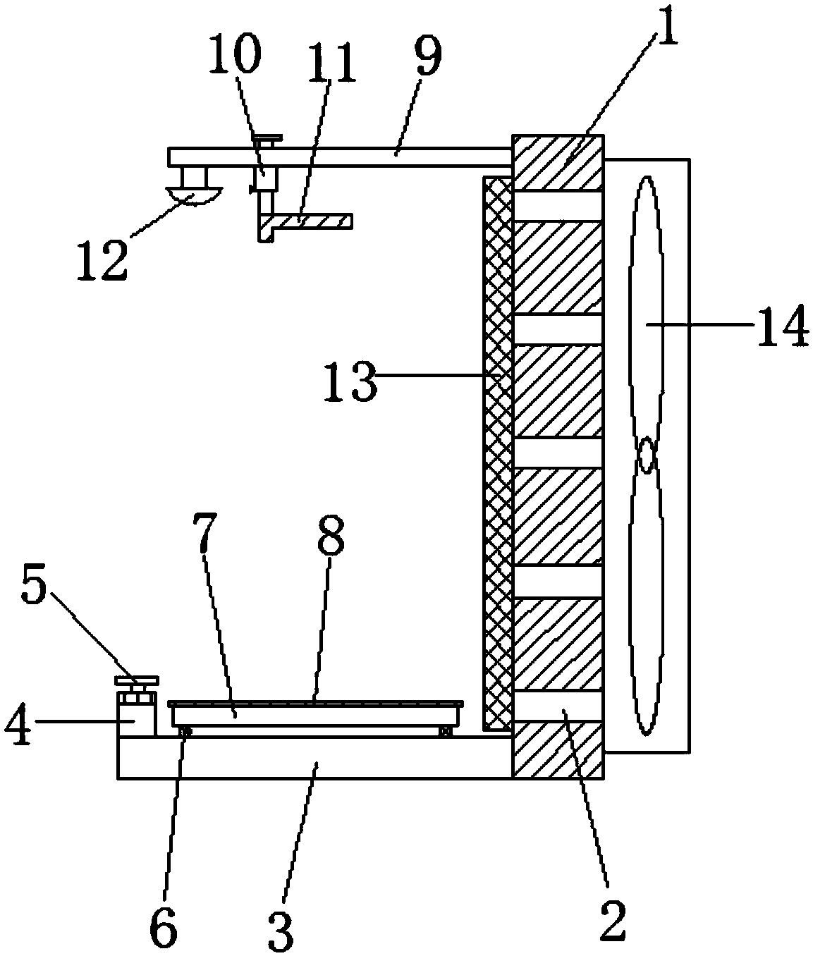
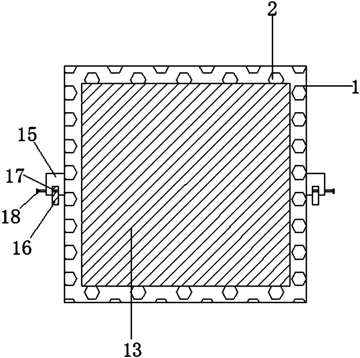
[0020] Such as Figure 1-2 As shown, a cooling frame for electric equipment includes a mounting plate 1, a support rod 3 is welded to one end of the mounting plate 1, a slider 4 is movably connected to the surface of the support rod 3, and a slider 4 is movably connected to one side of the slider 4. No. 6 roller, the surface of the No. 1 roller 6 is fixedly connected with a base 7, the other end of the mounting plate 1 is welded with a pole 9, the surface of the pole 9 is movably connected with a telescopic rod 10, and one end of the pole 9 is fixed A lighting lamp 12 is connected, one side of the telescopic rod 10 is provided with a cooling fin 13, one side of the cooling fin 13 is provided with a fan 14, and the other side of the cooling fin 13 ...


PUM


Abstract

The invention discloses an electric equipment radiating frame. The electric equipment radiating frame comprises a mounting plate, a support rod is welded at one end of the mounting plate, the surfaceof the support rod is movably connected with a sliding block, one side of the sliding block is movably connected with a No.1 roller, the surface of the No.1 roller is fixedly connected with a base, astrut is welded at the other end of the mounting plate; the surface of the strut is movably connected with a telescopic rod, one end of the strut is fixedly connected with a lighting lamp; radiating fins are arranged at one side of the telescopic rod, a fan is arranged at one side of the radiating fin, and a mounting lug is arranged at the other side of the radiating fin; the bottom surface of themounting lug is fixedly connected with a No.2 roller. The heat is dissipated to the surrounding air through the radiating fins, the air circulation is accelerated through the running of the fan, theradiating efficiency can be effectively improved, the use security of the transformer is improved, a positioning pin can penetrate a positioning hole after being rotated, the mounting plate can be effectively fixed, the operation is simple and convenient, and the mounting efficiency is improved.

Description

technical field [0001] The invention relates to a cooling rack, in particular to a cooling rack for electric equipment. Background technique [0002] The transformer is an important part of power equipment. The transformer is composed of an iron core and a coil. The coil has two or more windings. The winding connected to the power supply is called the primary coil, and the remaining windings are called the secondary coil. It can transform the AC voltage. , current and impedance. [0003] During the working process of the transformer, a large amount of heat will be generated inside. If the transformer is not dissipated, it will easily ignite spontaneously and cause a fire. The installation of the power equipment rack in the prior art is inconvenient. Due to the small space of the electric cabinet, the work efficiency is reduced. For this reason, we propose a cooling rack for electric equipment. Contents of the invention [0004] The main purpose of the present invention i...

Claims


Application Information

Patent Timeline
Patent Type & Authority Applications(China)
IPC IPC(8): H01F27/22H01F27/08H01F27/06
CPCH01F27/22H01F27/06H01F27/085
Inventor 陈为志
Owner 陈为志
Why Eureka
Try Eureka