Power supply wiring column structure and use method thereof

A technology of power supply wiring and column structure, applied in the direction of conductive connection, circuit, connection, etc., can solve the problem of relative rotation, and achieve the effect of avoiding relative rotation, high safety, and enhanced prevention.

Pending Publication Date: 2018-09-28
DONGFENG COMML VEHICLE CO LTD
View PDF4 Cites 2 Cited by
  • Summary
  • Abstract
  • Description
  • Claims
  • Application Information

AI Technical Summary

Problems solved by technology

[0007] The purpose of the present invention is to overcome the defects and problems existing in the prior art that the power terminal will rotate relatively during assembly and use, and provide a power terminal structure that does not relatively rotate during assembly and use and how to use it

Method used


Image

  • Power supply wiring column structure and use method thereof
  • Power supply wiring column structure and use method thereof
  • Power supply wiring column structure and use method thereof

Examples


Embodiment 1

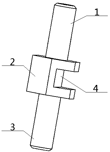
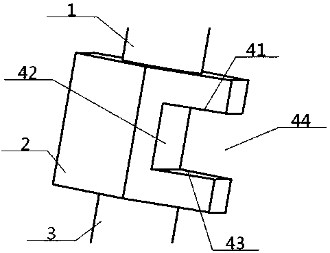
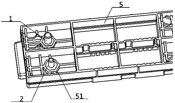
[0039] see Figure 1 to Figure 3 , a power terminal structure, including an upper thin column 1, a middle extension seat 2 and a lower thin column 3 (the upper thin column 1 and the lower thin column 3 are provided with threads), the bottom end of the upper thin column 1 and the middle The top surface of the extension seat 2 is connected, and the bottom surface of the middle extension seat 2 is connected with the top surface of the lower thin column 3; the side wall of the middle extension seat 2 is provided with a concave injection groove 4, and the injection groove 4 is a one-way The opening structure comprises an upper groove edge 41, a left groove bottom 42 and a lower groove edge 43, the inner end of the upper groove edge 41 is connected with the inner end of the lower groove edge 43 through the left groove bottom 42, and the outer end of the lower groove edge 43 is connected with the lower groove edge 43. A groove opening 44 is sandwiched between the outer ends of the up...

Embodiment 2

[0042] Basic content is the same as embodiment 1, the difference is:

[0043] The cross section of the upper thin column 1 and the lower thin column 3 is circular, oval or polygonal, the cross section of the middle extension seat 2 is circular, oval or polygonal, and the shape of the injection molding groove 4 is groove or wedge groove.

Embodiment 3

[0045] Basic content is the same as embodiment 2, the difference is:

[0046] The cross-section of the middle extension seat 2 is a regular hexagon; the shape of the injection molding groove 4 is an I-shaped groove, the left groove bottom 42 is rectangular, and the upper groove edge 41 and the lower groove edge 43 are both inner width Outer narrow isosceles trapezoid, the broad side on the upper groove edge 41, the lower groove edge 43 is vertically connected with the left groove bottom 42.


PUM


Abstract

Disclosed is a power supply wiring column structure. The power supply wiring column structure comprises an upper thin column, a middle epitaxial base and a lower thin column connected from the top tobottom in sequence; an inwardly concave injection molding groove is formed in the side periphery of the middle epitaxial base; the injection molding groove adopts a one-way opening structure and comprises an upper groove edge, a left groove bottom and a lower groove edge; the inner end of the upper groove edge is connected with the inner end of the lower groove edge through the left groove bottom;a groove opening is clamped between the outer end of the lower groove edge and the outer end of the upper groove edge; the upper thin column, the middle epitaxial base and the lower thin column are coaxially arranged; the radius of the middle epitaxial base is greater than that of the upper thin column and the lower thin column; and the horizontal distance between the shared axle wire of the upper thin column and the lower thin column and the left groove bottom is less than the radius of the upper thin column. By virtue of the design, it is ensured that the power supply wiring column does notrotate relatively in the assembling and use process, and relatively high safety, relatively high production efficiency and relatively low cost are achieved.

Description

technical field [0001] The invention relates to a terminal, which belongs to the field of automobile electrics, in particular to a structure of a power terminal and a method for using the same, and is particularly suitable for ensuring that the power terminal does not rotate relative to each other during assembly and use. Background technique [0002] With the improvement of people's demand for electricity and the increasingly harsh environment of vehicles, the requirements for power supply of the whole vehicle are increasing day by day, and the power terminal is an important part of the power distribution system. At present, the common power terminal on the market is cylindrical, and it is easy to rotate when it is combined with components such as power distribution boxes and SMJ boxes or when it is used later, resulting in unreliable connection of the power distribution system and prone to safety accidents. Specifically: [0003] First of all, the cylindrical power termina...

Claims


Application Information

Patent Timeline
Patent Type & Authority Applications(China)
IPC IPC(8): H01R4/30H01R9/00H01R9/16H01R43/24
CPCH01R4/305H01R9/00H01R9/16H01R43/24
Inventor 李静张亚晖严达袁中富胡磊
Owner DONGFENG COMML VEHICLE CO LTD
Why Eureka
Try Eureka