A Self-Generating Cable Communication Laying System

A cable communication and cable laying technology, applied in the direction of cable laying equipment, etc., can solve the problems of difficult handling, inconvenience, and large power generation mechanism, so as to avoid the operation of collecting and laying cables, ensure normal operation, and reduce friction.

Active Publication Date: 2020-03-27
山东克曼特新能源科技发展有限公司
View PDF6 Cites 0 Cited by
  • Summary
  • Abstract
  • Description
  • Claims
  • Application Information

AI Technical Summary

Problems solved by technology

However, if you need to move the bracket, bracket, or cable turntable, you need to move the bracket, bracket, or cable turntable as a whole, which is generally carried by hand, and the power for laying is still manually output, so it is difficult to move
[0006] Usually, cable laying is done in the field environment. During the laying operation, the communication between the laying personnel and the monitoring personnel of the upper computer is only based on the call of the mobile phone or walkie-talkie to complete the information communication.
Moreover, the cable laying equipment itself only realizes the task of laying, and cannot monitor the laying process, that is, during laying, it is impossible to obtain the length data of the laid cable, the data of the cable laying position, the laying atmospheric environment information, the laying geological information, etc. Data information, cable laying is only a single existing device, lacks linkage and interaction, and it is difficult to form a monitoring closed-loop network, making the laying process uncontrollable during laying
The use of communication and monitoring in field operations requires power supply guarantee. The guarantee of power supply is also an important part. If solar energy and wind energy are used, the power generation mechanism will be huge and not easy to carry. If gasoline engine or diesel engine is used, it is also not easy to carry.

Method used


Image

  • A Self-Generating Cable Communication Laying System
  • A Self-Generating Cable Communication Laying System
  • A Self-Generating Cable Communication Laying System

Examples


Embodiment Construction

[0070] In order to make the purpose, features and advantages of the present invention more obvious and understandable, the technical solutions protected by the present invention will be clearly and completely described below using specific embodiments and accompanying drawings. Obviously, the implementation described below Examples are only some embodiments of the present invention, but not all embodiments. Based on the embodiments in this patent, all other embodiments obtained by persons of ordinary skill in the art without making creative efforts belong to the scope of protection of this patent.

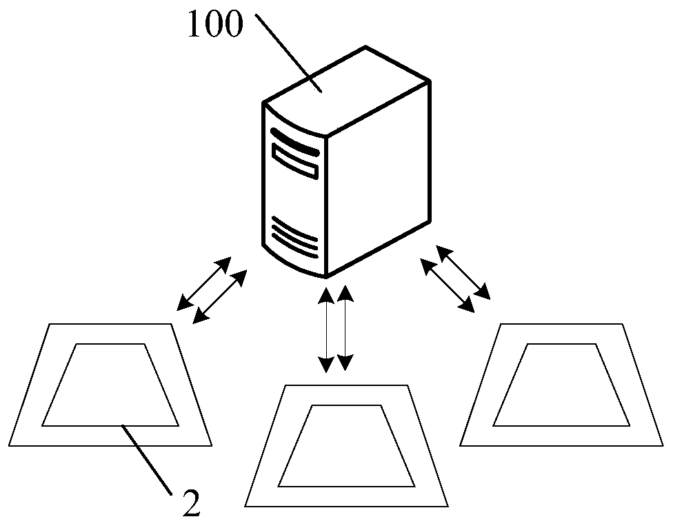
[0071] This embodiment provides a self-generating cable communication laying system, such as figure 1 , figure 2 As shown, it includes: a plurality of laying devices 1 that are installed outdoors for cable laying and a server 100 that is communicatively connected to each laying device 1;

[0072] A plurality of laying devices 1 are arranged in the cable laying area to perform la...


PUM


Abstract

The invention provides a cable communication laying system with an automatic power generation function. Each laying apparatus comprises a support assembly, a cable rotary plate placement mechanism used for placing a cable rotary plate, a walking mechanism, a driving motor, a speed reducer, a transmission mechanism, a storage battery, a power generation mechanism and a control mechanism; the powergeneration mechanism is connected with the storage battery; the storage battery supplies power for internal electrical components in the laying apparatus through a power supply circuit; the driving motor drives the walking mechanism to operate to move the laying apparatus through the speed reducer and the transmission mechanism; the laying apparatus can upload the laying condition to a server in real time through a wireless communication module to enable a monitoring staff to master the laying information in real time, so that position location of each laying apparatus can be performed, and onsite video information can be obtained; the support assembly is telescopic, so that the height can be adjusted, the cable collecting and releasing heights can be adjusted conveniently, and friction between the cable and the ground in dragging can be avoided and lowered; and in addition, the apparatus also can realize cable collecting and releasing in a driving manner, so that manual cable collecting and releasing can be avoided.

Description

technical field [0001] The invention relates to the field of cable laying, in particular to a self-generating cable communication laying system. Background technique [0002] The current way of cable laying is to wind the cable on the cable turntable. When the cable is laid, the cable is pulled by manpower, and the cable is released by turning the cable turntable. During the cable laying process, the cable is generally dragged on the ground, which not only consumes a lot of manpower, but also Dragging the cable on the ground will cause abrasion to the outer surface of the cable and affect the cable insulation. [0003] At present, based on the above problems, some materials improve the laying efficiency, and provide some laying methods such as: a simple bracket for cable laying, the bracket includes two vertically spaced columns, two fixed shafts and two rollers, There are through holes spaced apart on the uprights, the two fixed shafts penetrate through the through holes o...

Claims


Application Information

Patent Timeline
Patent Type & Authority Patents(China)
IPC IPC(8): H02G1/06
CPCH02G1/06
Inventor 申景光
Owner 山东克曼特新能源科技发展有限公司
Why Eureka
Try Eureka