A charging laser emitting device, receiving device, laser charging method and system

A laser emission and laser reception technology, applied in circuit devices, battery circuit devices, current collectors, etc., can solve problems such as damage, and achieve the effect of expanding the scope of early warning and improving safety

Active Publication Date: 2019-10-25
GREE ELECTRIC APPLIANCES INC
View PDF7 Cites 0 Cited by
  • Summary
  • Abstract
  • Description
  • Claims
  • Application Information

AI Technical Summary

Problems solved by technology

[0004] Embodiments of the present invention provide a charging laser emitting device, a receiving device, and a laser charging method and system to solve the problem of laser damage to nearby objects

Method used


Image

  • A charging laser emitting device, receiving device, laser charging method and system
  • A charging laser emitting device, receiving device, laser charging method and system
  • A charging laser emitting device, receiving device, laser charging method and system

Examples


Embodiment Construction

[0033] The present invention will be further described in detail below with reference to the accompanying drawings and specific embodiments. It should be understood that the specific embodiments described here are only used to explain the present invention, and are not intended to limit the present invention.

[0034] In the following description, the use of suffixes such as “module”, “part” or “unit” used to indicate elements is only for facilitating the description of the present invention, and has no specific meaning in itself. Therefore, "module", "part" or "unit" can be used in a mixed manner.

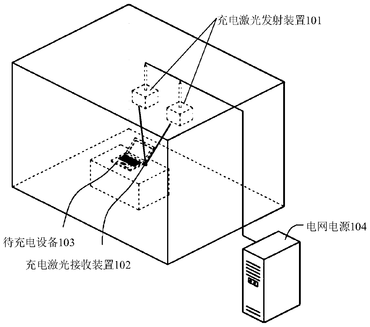
[0035] The embodiment of the present invention provides a schematic diagram of an application scenario of laser charging, such as figure 1 As shown, the application scenario includes a charging laser emitting device 101, a charging laser receiving device 102, a device to be charged 103, and a power grid 104.

[0036] In an example, there may be one or more charging laser emitting devices...


PUM


Abstract

The invention discloses a charging laser emitting device and receiving device as well as a laser charging method and system. The charging laser emitting device comprises a controller, an image sensorand a laser emitting device, wherein the image sensor is used for acquiring image data of an object within a preset range in a charging process and sending the image data to the controller; and the controller is used for judging whether the distance between the object and an action area of a charging laser beam is shortened or not according to the image data, and if yes, the controller controls the laser emitting device to suspend the emission of the charging laser beam. According to the scheme of the invention, the controller can accurately judge the movement trend of the object through the image data acquired by the image sensor, and can take safety measures in advance according to the movement trend of the object, which means controlling the suspension of the charging laser beam. Therefore, the invalidation of protection measures caused when the speed of the object is too fast can be avoided, an early warning range of the charging laser emitting device can be expanded, and the safety of the charging laser emitting device can be further improved.

Description

Technical field [0001] The invention relates to the field of charging technology, and in particular to a charging laser emitting device, a charging laser receiving device, a laser charging method and a laser charging system. Background technique [0002] At present, wired methods (for example, connecting the charger and electrical equipment through wires) or electromagnetic coupling methods are often used to charge electrical equipment. However, the above-mentioned charging method will cause greater radiation interference. In order to solve the above problems, laser charging technology came into being. However, the energy of the laser is highly concentrated, which can easily cause damage to objects close to the laser charging system. [0003] For the problem of how to effectively avoid laser damage to nearby objects, no effective solutions have been proposed. Summary of the invention [0004] In the embodiments of the present invention, a charging laser emitting device, a receivi...

Claims


Application Information

Patent Timeline
Patent Type & Authority Patents(China)
IPC IPC(8): H02J7/00H02J50/90H02J50/30
CPCH02J7/025H02J50/30H02J50/90
Inventor 莫飞凡牟桂贤符胜蒋彪李窑
Owner GREE ELECTRIC APPLIANCES INC
Why Eureka
Try Eureka