Stacking equipment for motor rotor cores

A rotor core and motor technology, which is applied in the field of iron core stacking, can solve the problems of silicon steel sheet detection interference, silicon steel sheet quality damage, and low positioning accuracy of silicon steel sheets, so as to achieve high stacking accuracy and improve stacking efficiency Effect

Active Publication Date: 2018-09-28
上海发腾航空科技股份有限公司
View PDF6 Cites 2 Cited by
  • Summary
  • Abstract
  • Description
  • Claims
  • Application Information

AI Technical Summary

Problems solved by technology

The utility model is applied in the field of iron core production, and effectively solves the problems of on-line detection interference of silicon steel sheets, inability to realize online classification and sorting, serious damage to the quality of silicon steel sheets during stacking, etc.
However, there are the following disadvantages: 1. The continuity is poor during stacking. When a stack of silicon steel sheets is completed, it needs to be shut down for a long time to replace the rotor shaft; 2. The positioning accuracy of the silicon steel sheets is low, so when stacking silicon steel sheets, the The side of the sheet is not neat, which is not conducive to the winding work of the iron core in the later stage

Method used


Image

  • Stacking equipment for motor rotor cores
  • Stacking equipment for motor rotor cores
  • Stacking equipment for motor rotor cores

Examples


Embodiment Construction

[0023] The technical solutions in the embodiments of the present invention will be clearly and completely described below in conjunction with the embodiments of the present invention. Apparently, the described embodiments are only some of the embodiments of the present invention, not all of them. Based on the embodiments of the present invention, all other embodiments obtained by persons of ordinary skill in the art without making creative efforts belong to the protection scope of the present invention.

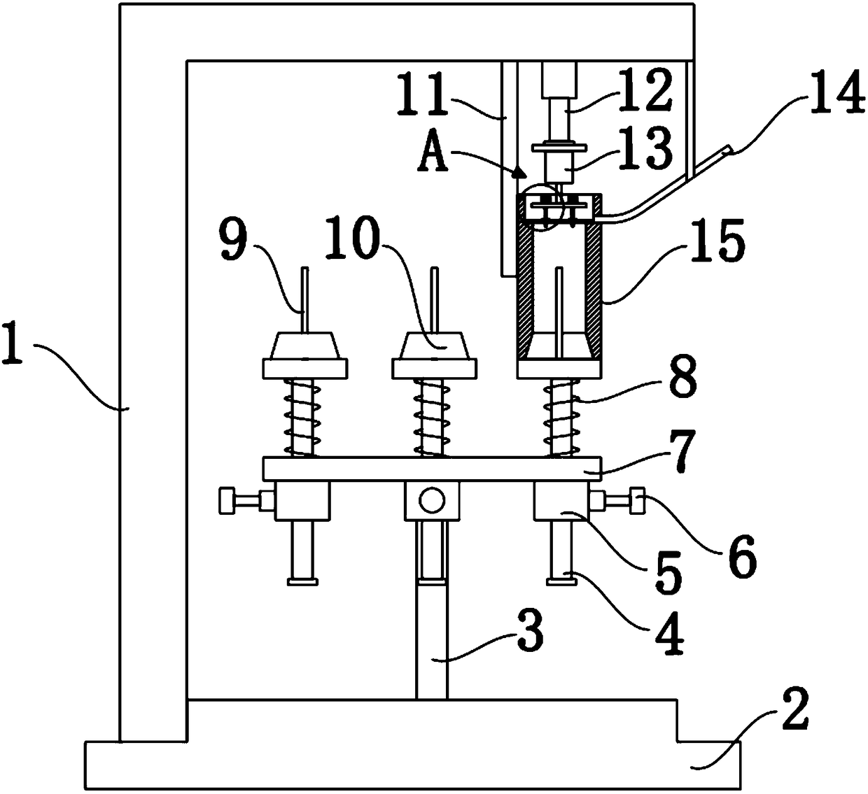
[0024] Such as Figure 1-4 As shown, a motor rotor core stacking equipment, including:

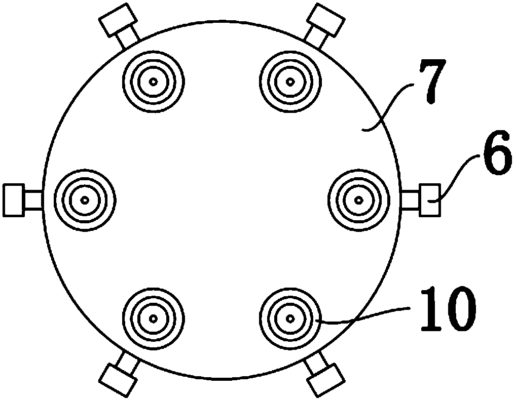
[0025] The tray 7, the center of the tray 7 is connected to the base 2 through the support shaft 3, the lower surface of the tray 7 is welded and fixed with a sliding sleeve 5, and the sliding sleeve 5 is connected with a push rod 4 inside, and the push rod 4 A support platform 10 is fixed on the top of the support platform 10, and a rotor shaft 9 is installed at the center of the suppor...


PUM


Abstract

The invention discloses stacking equipment for motor rotor cores. The equipment comprises a tray and a bushing, wherein the center of the tray is rotationally connected to a base through a support shaft, sliding sleeves are welded and fixed on the lower surface of the tray, ejector rods are glidingly connected in the sliding sleeves, and rotor rotating shafts are installed at the centers of support platforms; a motor is connected to a support arm through a hydraulic cylinder, an output shaft of the motor extends into the upper end of the bushing and is provided with a support plate, and guidepins are movably connected with two ends of the support plate. The guide pins on the support plate are driven by the motor to rotate, positions of silicon steel sheets can be adjusted, the silicon steel sheets are automatically installed on rotor rotating shafts in the same posture, and accordingly, stacking efficiency of the rotor cores is improved, and stacking precision is high; after the coreson the rotor rotating shafts are stacked, the tray is rotated, unloaded support platforms are replaced in the bushing, the rotor rotating shafts loaded with the cores are then replaced, and next corestacking is started. The equipment has the advantages of short downtime and high continuity during stacking.

Description

technical field [0001] The invention belongs to the technical field of iron core stacking, in particular to a motor rotor iron core stacking equipment. Background technique [0002] Motors are widely used in various electrical equipment in industrial production and life. The existing motors have a stator and a rotor. The rotor shaft is installed in the rotor and rotates with the rotation of the rotor, thereby outputting power. According to the positional relationship between the rotor and the stator, existing motors are divided into inner rotor motors and outer rotor motors. The rotor of the inner rotor motor is installed in the stator, while the outer rotor motor has the stator installed in the rotor. [0003] At present, the silicon steel sheets of the motor rotor are provided with slots for winding coils. When stacking the silicon steel sheets, it is necessary to align the slots on each silicon steel sheet with the same posture to fix the silicon steel sheets. For exampl...

Claims


Application Information

Patent Timeline
IPC IPC(8): H02K15/02
CPCH02K15/02
Inventor 闫毛钦李夫
Owner 上海发腾航空科技股份有限公司
Why Eureka
Try Eureka