Connecting structure and guide wire having the connecting structure
A structure and metal connection technology, applied in the direction of manufacturing tools, guide wires, household appliances, etc., can solve problems such as bending of flexible shafts, and achieve the effect of easy follow-up and improved flexibility
- Summary
- Abstract
- Description
- Claims
- Application Information
AI Technical Summary
Problems solved by technology
Method used
Image
Examples
no. 1 approach
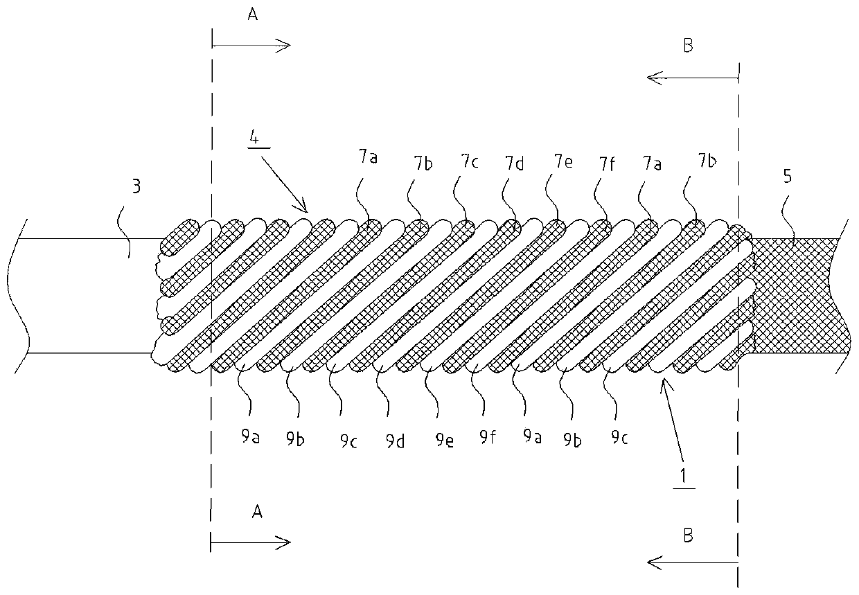
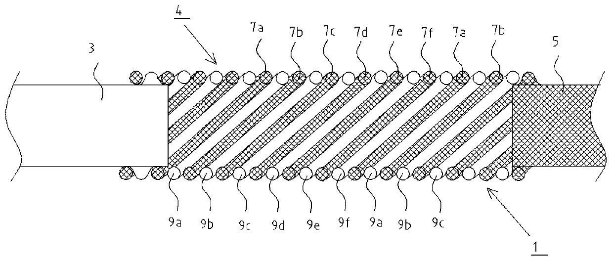
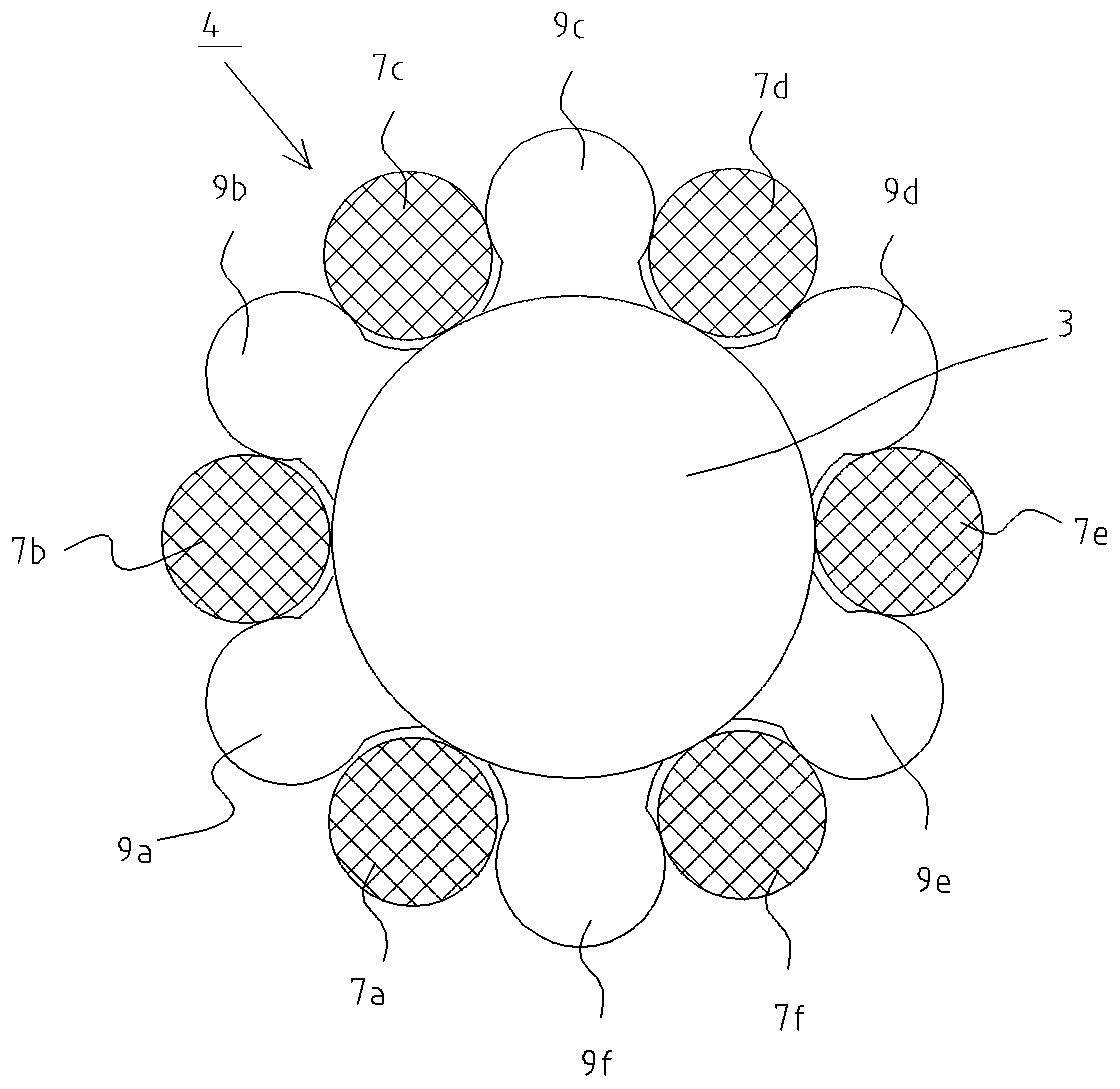
[0033] figure 1 It is a side view of the connection structure of the first embodiment of the present invention, figure 2 is a side sectional view of the connection structure of the first embodiment, image 3 yes figure 1 The A-A sectional view of Figure 4 yes figure 1 BB sectional view of .
[0034] In addition, in this embodiment, the materials of the first rod 3 and the first metal wire 9 described later are the same, and the materials of the second rod 5 and the second metal wire 7 described later are the same for easy recognition. , only the second bar 5 and the second metal wire 7 are hatched in a mesh shape.
[0035] exist figure 1 as well as figure 2 Among them, the connection structure 1 connecting two metal rods is used to connect the first rod 3 made of stainless steel alloy and the second rod 5 made of nickel-titanium alloy, and the first rod 3 and the second rod Between the materials 5, a plurality of coils 4 are connected, and the plurality of coils 4 a...
no. 2 approach
[0050] Figure 5 is a side view of the connection structure of the second embodiment, Figure 6 It is a side sectional view of the connection structure of 2nd Embodiment.
[0051] In addition, in this embodiment, the materials of the third rod 23 and the third metal wire 29 described later are also the same, and in order to easily identify the materials of the fourth rod 25 and the fourth metal wire 27 described later, Similarly, mesh hatching is given only to the fourth bar 25 and the fourth metal wire 27 .
[0052] exist Figure 5 as well as Figure 6 Among them, the connection structure 21 connecting two metal rods is used to connect the third rod 23 made of stainless steel alloy and the fourth rod 25 made of nickel-titanium alloy, and the third rod 23 and the fourth rod Between the materials 25, a plurality of coils 24 are connected, and the plurality of coils 24 are formed by winding a third metal wire 29 made of a stainless steel alloy and a fourth metal wire 27 made...
no. 3 approach
[0066] Figure 7 is a schematic side view of the guide wire of the third embodiment, Figure 8 It is a schematic side sectional view of the guide wire of the third embodiment.
[0067] In addition, in this embodiment, the first cylindrical portion 33a, the first tapered portion 33b, the second cylindrical portion 33c, the second tapered portion 33d, and the third cylindrical portion of the core shaft 33 described later 33e and the fifth metal wire 39 are made of the same material. In order to easily identify the material of the fourth cylindrical portion 33g of the mandrel 33 described later and the material of the sixth metal wire 37 are the same, only the fourth cylindrical portion of the mandrel 33 33g and the sixth metal wire 37 are hatched in a mesh shape.
[0068] exist Figure 7 as well as Figure 8 Among them, the guide wire 40 includes a mandrel 33 and a coil body 48 covering the tip of the mandrel 33 .
[0069] The coil body 48 is a single coil body made of a st...
PUM
 Abstract
Description
Claims
Application Information
 - R&D
- Intellectual Property
- Life Sciences
- Materials
- Tech Scout
- Unparalleled Data Quality
- Higher Quality Content
- 60% Fewer Hallucinations
Browse by: Latest US Patents, China's latest patents, Technical Efficacy Thesaurus, Application Domain, Technology Topic, Popular Technical Reports.
© 2025 PatSnap. All rights reserved.Legal|Privacy policy|Modern Slavery Act Transparency Statement|Sitemap|About US| Contact US: help@patsnap.com


