Mechanical sealing arrangement with a simplified structure

A mechanical seal device and a technology for sealing gaps, which is applied to engine seals, mechanical equipment, engine components, etc., and can solve problems such as difficulty in pulling off the mechanical seal device

Inactive Publication Date: 2018-09-28
EAGLEBURGMANN GERMANY GMBH &CO KG
View PDF12 Cites 3 Cited by
  • Summary
  • Abstract
  • Description
  • Claims
  • Application Information

AI Technical Summary

Problems solved by technology

This can cause difficulties when the mechanical seal is pulled off axially

Method used


Image

  • Mechanical sealing arrangement with a simplified structure
  • Mechanical sealing arrangement with a simplified structure

Examples


Embodiment Construction

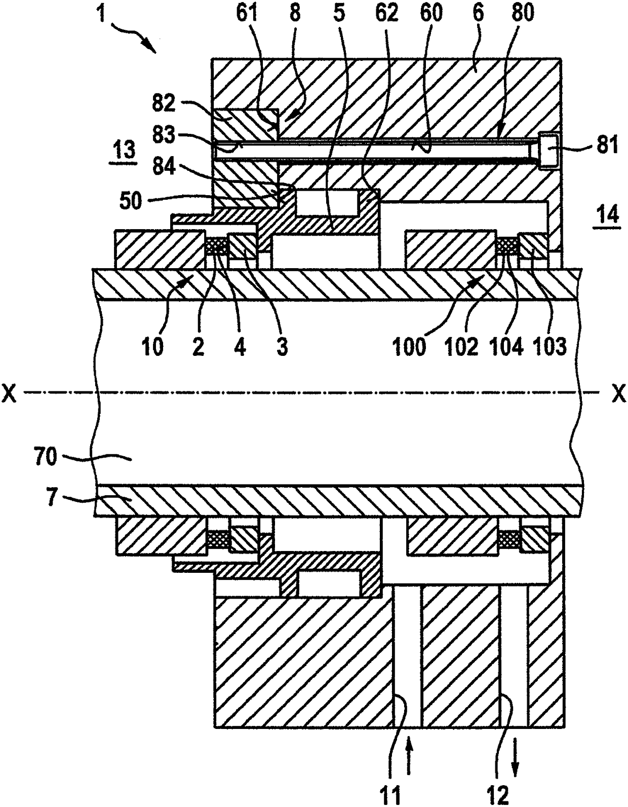
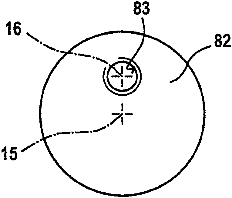
[0021] Below, based on figure 1 and figure 2 A mechanical seal device 1 according to a preferred exemplary embodiment of the present invention will be described in detail.

[0022] Such as figure 1 As shown, the mechanical seal device 1 includes a first mechanical seal 10 and a second mechanical seal 100 . The first mechanical seal 10 includes a rotating slip ring 2 and a fixed slip ring 3 , and a sealing gap 4 is defined between the rotating slip ring 2 and the fixed slip ring 3 . The second mechanical seal 100 includes a rotating slip ring 102 and a fixed slip ring 103 , and a sealing gap 104 is defined between the rotating slip ring 102 and the fixed slip ring 103 .

[0023] The mechanical seal 1 seals the product side 13 against the atmosphere side 14 at the shaft 70 .

[0024] Mechanical seals are preferably used in pumps and the like.

[0025] Such as figure 1 As shown, the mechanical seal device is installed on the shaft sleeve 7 . The mechanical seal 1 is provi...


PUM


Abstract

The invention relates to a slip ring sealing arrangement (1) comprising a rotating slip ring (2) and a stationary slip ring (3) which define a sealing gap (4) thereinbetween, a holding ring (5) for holding the stationary slip ring (3), a housing (6) with one side oriented towards a product side (13) and one side oriented towards an atmosphere side (14), and a clamping device (8), wherein a clamping connection is embodied between the housing (6) and the holding ring (5) by means of the clamping device (8), and the housing (6) has at least one through-opening (60) which connects the side of thehousing oriented towards the product side (13) to the side of the housing oriented towards the atmosphere side (14), the clamping device (8) comprising a screwed bolt (80) and a clamping element (82),the screwed bolt (80) being arranged in the through-opening (60) of the housing (6), and the clamping element (82) comprising a threaded opening (83) in which the screwed bolt (80) is screwed, and wherein the clamping element (82) has a gripping surface (84) applied to the holding ring (5) in order to form the clamping connection.

Description

technical field [0001] The present invention relates to a mechanical seal having a simple structure, wherein in particular the mechanical seal can be easily disassembled from the atmosphere side. Background technique [0002] Mechanical seals are known from the prior art in various embodiments. A mechanical seal with a retaining ring for holding a stationary slip ring is known, for example, from DE 10 2013 007 165 B4, wherein the retaining ring is connected to the housing by means of a clamp connection. Furthermore, the clamp connection is arranged on the product side of the mechanical seal. In this way, the necessary supply lines can be freely arranged inside the housing, so that in particular various customer wishes can be realized when the supply lines are arranged. Also, the mechanical seal device is attached to a shaft or the like in the axial direction. After a certain number of operating hours, it may be necessary to replace the slip rings and other worn parts of t...

Claims


Application Information

Patent Timeline
Patent Type & Authority Applications(China)
IPC IPC(8): F16J15/34
CPCF16J15/3464
Inventor J·格尔格B·哈姆
Owner EAGLEBURGMANN GERMANY GMBH &CO KG
Why Eureka
Try Eureka