Load control system having visible light sensor

A sensor and visible light technology, applied in general control systems, control/regulation systems, program control, etc., can solve problems such as inefficient information communication, inaccurate information, and inaccurate load control

Active Publication Date: 2018-09-28
LUTRON TECH CO LLC
View PDF24 Cites 1 Cited by
  • Summary
  • Abstract
  • Description
  • Claims
  • Application Information

AI Technical Summary

Problems solved by technology

[0010] Since complex load control systems often include many different types of input devices used to gather information about the load control environment, processing and communicating information in such systems can be inefficient
Also, since the information collected by many input devices may not be accurate, the control of the load based on such information may also be inaccurate

Method used


Image

  • Load control system having visible light sensor
  • Load control system having visible light sensor
  • Load control system having visible light sensor

Examples


Embodiment Construction

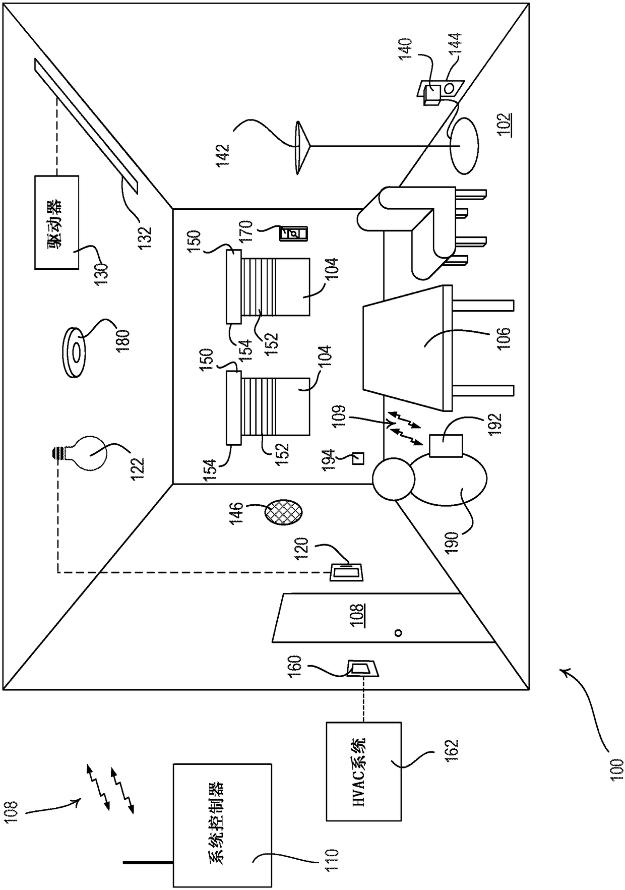
[0031] figure 1is a simplified diagram of an example load control system 100 for controlling the amount of power delivered to one or more electrical loads from an alternating current (AC) power source (not shown). The load control system 100 may be installed in a room 102 of a building. The load control system 100 may include multiple control devices configured to communicate with each other via wireless signals (eg, radio frequency (RF) signals 108 ). Alternatively or additionally, the load control system 100 may include a wired digital communication link coupled to one or more control devices to provide communication between the load control devices. The control devices of the load control system 100 may include multiple control source devices (e.g., input devices operable to send digital messages in response to user input, occupancy / vacancy conditions, changes in measured light intensity, etc.) and multiple control source devices. A target device (eg, a load control devic...


PUM


Abstract

A sensor (180) for sensing environmental characteristics of a space (102) may include a visible light sensing circuit for recording an image of the space and a control circuit responsive to the visible light sensing circuit. The control circuit may detect an occupancy or vacancy condition in the space in response to the visible light sensing circuit, and measure a light level in the space in response to the visible light sensing circuit. The control circuit may also include a low-energy occupancy sensing circuit for detecting an occupancy condition in the space. The control circuit may disablethe visible light sensing circuit when the space is vacant. The control circuit may detect an occupancy condition in the space in response to the low-energy occupancy sensing circuit and subsequentlyenable the visible light sensing circuit. The visible light sensor may be configured in a way that protects the privacy of the occupants of the space.

Description

[0001] Cross References to Related Applications [0002] This application claims priority to US Provisional Patent Application No. 62 / 266,370, filed December 11, 2015. technical field Background technique [0003] For example, various types of load control systems may be used to configure user environments (eg, residential or office buildings). A lighting control system may be used to control lighting loads that provide artificial light within a user's environment. Motorized shades can be used to control the natural light provided to the user's environment. HVAC systems can be used to control the temperature within a user's environment. [0004] Each load control system may include various control devices, including input devices and load control devices. A load control device may receive digital messages, which may include load control instructions, for controlling electrical loads from one or more input devices. Load control devices are capable of directly controlling ...

Claims


Application Information

Patent Timeline
Patent Type & Authority Applications(China)
IPC IPC(8): H05B37/02G08B13/196F21V23/04H04N7/18
CPCH04N7/188H05B47/105H05B47/19H05B47/125Y02B20/40H05B47/11H05B47/18H05B47/115G06V40/20G05B19/048G05B2219/23153
Inventor 詹姆斯·P·斯坦纳
Owner LUTRON TECH CO LLC
Why Eureka
Try Eureka