
Hydraulic type component clamping device for chemical industry processing

A hydraulic and component clamping technology, which is applied in the direction of workpiece clamping devices and manufacturing tools, can solve the problems of thread damage, poor clamping force, etc., achieve long service life, simple operation, and realize the effect of reset function

Inactive Publication Date: 2018-10-02
薛春红
View PDF6 Cites 4 Cited by
  • Summary
  • Abstract
  • Description
  • Claims
  • Application Information

AI Technical Summary

Problems solved by technology

[0002] At present, in chemical enterprises, when some chemical equipment needs to be disassembled and columnar, clamping devices are required, because some equipment is soaked and exposed to corrosive and toxic raw materials used in some chemical industries, so in order to ensure The health of the staff requires that the parts be clamped into the clamping device to realize disassembly and installation. However, the existing clamping devices use threads for clamping, so long-term work causes damage to the threads, and the clamping poor strength

Method used


Image

  • Hydraulic type component clamping device for chemical industry processing
  • Hydraulic type component clamping device for chemical industry processing
  • Hydraulic type component clamping device for chemical industry processing

Examples


Embodiment Construction

[0018] The following will clearly and completely describe the technical solutions in the embodiments of the present invention with reference to the accompanying drawings in the embodiments of the present invention. Obviously, the described embodiments are only some, not all, embodiments of the present invention. Based on the embodiments of the present invention, all other embodiments obtained by persons of ordinary skill in the art without making creative efforts belong to the protection scope of the present invention.

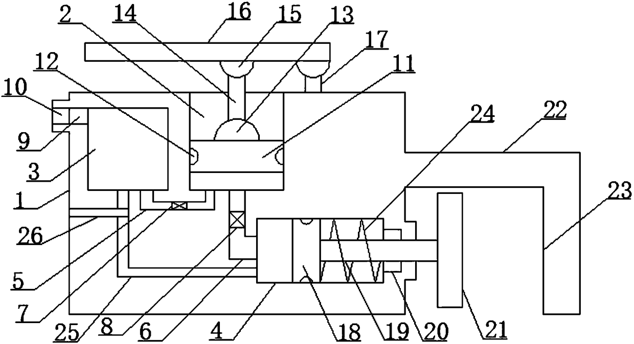
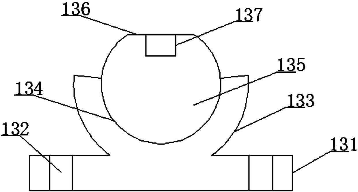
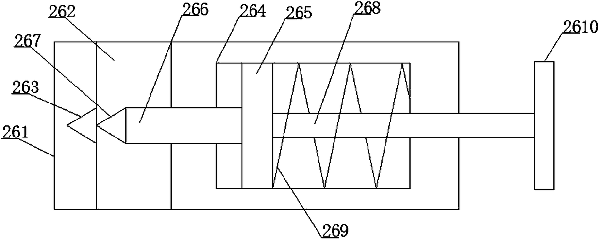
[0019] see figure 1, an embodiment provided by the present invention: comprising a main hollow shell 1, the center of the upper surface of the main hollow shell 1 is provided with a liquid compression space 2, and the interior of the main hollow shell 1 is located in the liquid compression space 2 One side is provided with a liquid storage space 3, the level of the bottom of the liquid storage space 3 is consistent with the level of the bottom of the liquid co...


PUM


Abstract

The invention discloses a hydraulic type component clamping device for chemical industry processing. The hydraulic type component clamping device for chemical industry processing comprises a main hollow shell. Liquid compression space is formed in the center of the upper surface of the main hollow shell. Liquid storage space is formed in the part, located on the side with the liquid compression space, of the interior of the main hollow shell. The hydraulic type component clamping device for chemical industry processing achieves the clamping function with high control capacity by utilizing hydraulic pressure, and then achieves oriented flow of liquid by utilizing the lever principle, the clamping positioning function in a hydraulic manner is achieved; and the hydraulic type component clamping device for chemical industry processing has the characteristics of being easy to operate, long in service life, stable in work, and is high in practicability. Furthermore, the hydraulic type component clamping device for chemical industry processing is provided with a universal rotary guide connection mechanism, and thereby being capable of converting motion, coming from the position above andhaving a certain rotation angle, into reciprocating compression of vertical motion, so that a press rod is capable of driving a main piston plate, and the function of oriented liquid compression is achieved. In addition, because the hydraulic type component clamping device for chemical industry processing is provided with a liquid instantaneous opening and closing control mechanism, quick and effective instantaneous work can be achieved, and the reset function of liquid is achieved.

Description

technical field [0001] The invention relates to the technical field of chemical equipment, in particular to a hydraulic component clamping device for chemical industry processing. Background technique [0002] At present, in chemical enterprises, when some chemical equipment needs to be disassembled and columnar, clamping devices are required, because some equipment is soaked and exposed to corrosive and toxic raw materials used in some chemical industries, so in order to ensure The health of the staff requires that the parts be clamped into the clamping device to realize disassembly and installation. However, the existing clamping devices use threads for clamping, so long-term work causes damage to the threads, and the clamping Poor strength. Contents of the invention [0003] The object of the present invention is to provide a hydraulic component clamping device for chemical industry processing to solve the problems raised in the above-mentioned background technology. ...

Claims


Application Information

Patent Timeline
Patent Type & Authority Applications(China)
IPC IPC(8): B25B11/02
CPCB25B11/02
Inventor 薛春红
Owner 薛春红
Learn More