Eureka AIR delivers breakthrough ideas for toughest innovation challenges, trusted by R&D personnel around the world.

Anti-collision device for ship port

An anti-collision device and port technology, applied in shipping equipment, climate change adaptation, etc., can solve problems such as rubber hardening and aging, collision between ships and dock facilities, and ship size and driver's nervousness, so as to avoid collisions and increase resistance. Effect

Active Publication Date: 2021-05-04
陈忠响
View PDF6 Cites 2 Cited by
  • Summary
  • Abstract
  • Description
  • Claims
  • Application Information

AI Technical Summary

Problems solved by technology

As a free body floating in the water, the ship will produce serious swaying motion under the action of external wind, waves and currents, especially in the port area. Due to the large and complex size of the ship, it is easy to cause the driver's emotional tension, which will affect the rationality of the ship's control; at the same time The underwater hydrological environment is very complicated, that is, the direction of the water flow is unstable. When other ships pass by, the fluctuation of the water sometimes suddenly pushes the ship to the dock and then collides, or the underwater water flow suddenly changes direction, causing the tugboat to push When the ship docks at the dock, the resistance on the tugboat suddenly decreases, causing the ship to collide with the dock facilities, causing damage to the ship, dock and dock equipment
In order to avoid this kind of phenomenon or weaken its damage effect, people have designed many anti-collision devices, such as setting waste tires beside the wharf, but due to the singleness of its anti-collision principle, its effect is not ideal; Rubber items are used for cushioning. Due to wind, sun, and seawater immersion, the rubber hardens and ages quickly.

Method used


Image

  • Anti-collision device for ship port
  • Anti-collision device for ship port

Examples


Embodiment 1

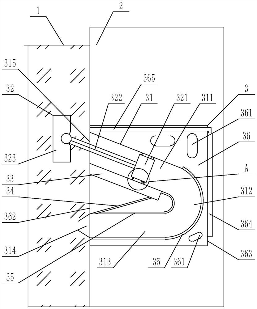
[0042] An anti-collision device for a ship port, which is connected to a dock foundation under the water surface, and the anti-collision device for a ship port includes a channel and an anti-collision assembly;

[0043] The passage includes a horizontal part, an inclined part and a transfer part, the horizontal part includes a water outlet end and a first connection end, the water outlet end is an end away from the foundation of the pier, and the inclined part includes a water inlet end and a second connection end end, the channel formed by connecting the first connection end and the second connection end through the transfer part is a horizontal V-shaped structure with openings at both ends;

[0044] The opening of the water outlet end is smaller than the opening of the water inlet end, and a limit block is arranged on the opening of the water inlet end;

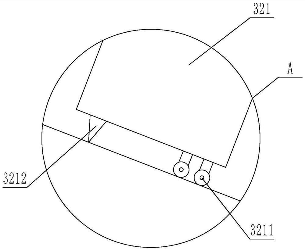
[0045] The anti-collision assembly includes a slider, a rigid connecting rod and a flexible stopper, the slider is slidab...


PUM


Abstract

The invention relates to the technical field of wharf anti-collision technology, in particular to a ship port anti-collision device, which is connected to the foundation of the wharf under the water surface. The ship port anti-collision device includes a channel and an anti-collision assembly; part and a transfer part, the channel formed by connecting the horizontal part and the inclined part through the transfer part is a horizontal V-shaped structure with openings at both ends; the opening of the water outlet end is smaller than the opening of the water inlet end, and the opening of the water inlet end The limit block is set on the top; the anti-collision assembly includes a slider, a rigid link and a flexible stopper, the slider is slid inside the inclined part, the flexible stopper is set outside the channel, and the flexible stopper is connected through a rigid link. The rod is connected with the slider; the density of the flexible stopper is lower than the density of water; the present invention converts the collision energy of the ship into the energy of impact towards the ship through the anti-collision assembly, changes and stabilizes the direction of the water flow, and at the same time, the water flow has the ability to move the ship toward the ship. The energy pushed out makes the ship dock stably.

Description

technical field [0001] The invention relates to the technical field of wharf anti-collision, in particular to a ship port anti-collision device. Background technique [0002] With the improvement of the economic level, more and more goods are transported to all parts of the world by large cargo ships. As a free body floating in the water, the ship will produce serious swaying motion under the action of external wind, waves and currents, especially in the port area. Due to the large and complex size of the ship, it is easy to cause the driver's emotional tension, which will affect the rationality of the ship's control; at the same time The underwater hydrological environment is very complicated, that is, the direction of the water flow is unstable. When other ships pass by, the fluctuation of the water sometimes suddenly pushes the ship to the dock and then collides, or the underwater water flow suddenly changes direction, causing the tugboat to push When the ship docks at t...

Claims


Application Information

Patent Timeline
Patent Type & Authority Patents(China)
IPC IPC(8): E02B3/26
CPCE02B3/26Y02A30/30
Inventor 陈忠响
Owner 陈忠响
Why Eureka
Eureka Blog
Learn More