Automatic metal cutting device

A metal cutting and cutting table technology, applied in positioning devices, metal processing, metal processing equipment, etc., can solve the problems of low degree of automation, low cutting efficiency, high labor intensity, etc., and achieve high degree of automation, low labor intensity, and reduced The effect of labor intensity

Active Publication Date: 2021-01-29
WENZHOU UNIVERSITY
View PDF6 Cites 2 Cited by
  • Summary
  • Abstract
  • Description
  • Claims
  • Application Information

AI Technical Summary

Problems solved by technology

[0003] The purpose of the present invention is to solve the shortcomings of low cutting efficiency, low precision, high

Method used


Image

  • Automatic metal cutting device
  • Automatic metal cutting device
  • Automatic metal cutting device

Examples


Embodiment 1

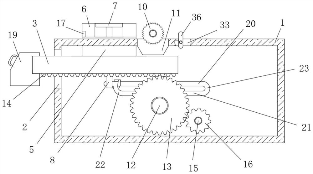
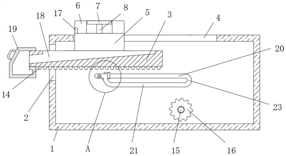
[0033] refer to Figure 1-8 , an automatic metal cutting device, including a cutting table 1, and the cutting table 1 is a hollow structure, a through hole 2 is opened on one side of the cutting table 1, and a moving plate 3 is slidably connected in the through hole 2, and the cutting table 1 Two moving holes 4 are opened symmetrically on the top, one side of the top of the moving plate 3 extends to the inside of the cutting table 1 and two moving blocks 5 are fixedly connected symmetrically, and one side of the two moving blocks 5 passes through the corresponding moving holes 4 respectively And both extend to the top of the cutting table 1, the tops of the two moving blocks 5 are fixedly connected with a baffle plate 6 on the side away from each other, and the tops of the two baffle plates 6 are slidably connected with a pressure plate 7 on the side close to each other. The bottom of the pressing plate 7 is fixedly connected with a pressing rod 8, and the bottom ends of the t...

Embodiment 2

[0035] Further improved on the basis of embodiment one:

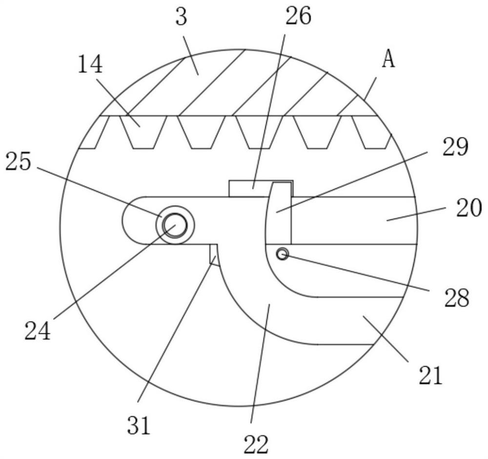
[0036] In the present invention, the drive assembly includes a first rotating rod 12 that is rotatably connected to the inside of the cutting table 1. A large gear 13 is fixedly sleeved on the first rotating rod 12. A rack 14 is provided at the bottom of the moving plate 3, and the rack 14 Engage with the large gear 13, the bottom of the inner wall of one side of the cutting table 1 is fixedly connected with a servo motor 15, the output shaft of the servo motor 15 is fixedly provided with a pinion 16, and the pinion 16 is meshed with the large gear 13, and the start The servo motor 15 can drive the bull gear 13 to realize differential rotation through the meshing motion of the pinion 16 and the bull gear 13. When the bull gear 13 rotates, the meshing motion with the rack 14 can drive the moving plate 3 to move.

[0037] In the present invention, the top of the moving plate 3 is provided with a debris diversion groove 18...


PUM


Abstract

The invention belongs to the technical field of a metal cutting device, and particularly relates to an automatic metal cutting device. For the problems of low cutting efficiency, low precision, high labor intensity, high hazard and low degree of automation in the prior art, the invention proposes the following scheme that the automatic metal cutting device comprises a cutting table; the cutting table is of a hollow structure; a through hole is formed on the top of one side of the cutting table; a moving plate is in sliding connected into the through hole in a penetrating mode; and two moving holes are symmetrically formed on the top of the cutting table. In the invention, by starting a servo motor, not only can the moving plate be driven to move and the automatic feeding effect is achieved, but also the effect of automatically clamping a plate can be achieved through cooperation of a pressing rod and a pressing plate in the feeding process, the automatic discharging effect can be achieved through a rotating block; the automatic metal cutting device is high in automation degree in the whole process and easy to operate; hand pressing feeding does not need to be carried out; labor intensity is low; safety is high; and the cutting efficiency and the cutting precision are greatly improved.

Description

technical field [0001] The invention relates to the technical field of metal cutting devices, in particular to an automatic metal cutting device. Background technique [0002] At present, there are two cutting methods of manual cutting and mechanical cutting for sheet metal cutting. Manual cutting is time-consuming, labor-intensive, inefficient, and has low cutting accuracy; while mechanical cutting requires manual feeding, although compared with manual cutting, the cutting efficiency is improved, but such an operation is dangerous, and it is easy to cause injury to the operator. It is still not high, the cutting parts are uneven, and the labor intensity of hand pressing the plate is still high, and the degree of automation is low. Therefore, we propose an automatic metal cutting device to solve the above-mentioned problems. Contents of the invention [0003] The purpose of the present invention is to solve the shortcomings of low cutting efficiency, low precision, high l...

Claims


Application Information

Patent Timeline
IPC IPC(8): B23Q7/00B23Q3/06B23Q11/00
CPCB23Q3/06B23Q7/00B23Q11/0067
Inventor 陈益丰朱立志饶道团潘晓铭陈雷清
Owner WENZHOU UNIVERSITY
Why Eureka
Try Eureka