Automatic electroplating machine capable of being used for irregular parts and facilitating clamping

An irregular electroplating machine technology, applied in plating tanks, electrolytic processes, electrolytic components, etc., can solve the problems of weak continuous electroplating ability, inaccurate electroplating time operation, and consumption of manpower and material resources. Maintaining stability and improving efficiency

Active Publication Date: 2018-10-02
江门市美浩伦电镀有限公司
View PDF11 Cites 1 Cited by
  • Summary
  • Abstract
  • Description
  • Claims
  • Application Information

AI Technical Summary

Problems solved by technology

[0007] Most of the existing electroplating machines include an electroplating pool, and most of them directly clamp the product into the electroplating pool through tweezers for electroplating. After a period of electroplating, the product is taken out, which consumes a lot of manpower and material resources. At the same time, the electroplating efficiency is not high. The ability of continuous electroplating is not strong, and a certain time gap is required for the product to be picked and placed. At the same time, the time operation of electroplating is not accurate, resulting in inaccurate electroplating, which in turn affects the effect of electroplating

Method used


Image

  • Automatic electroplating machine capable of being used for irregular parts and facilitating clamping
  • Automatic electroplating machine capable of being used for irregular parts and facilitating clamping
  • Automatic electroplating machine capable of being used for irregular parts and facilitating clamping

Examples


Embodiment Construction

[0037]In order to enable those skilled in the art to better understand the technical solution of the present invention, the present invention will be described in detail below in conjunction with the accompanying drawings. The description in this part is only exemplary and explanatory, and should not have any limiting effect on the protection scope of the present invention. .

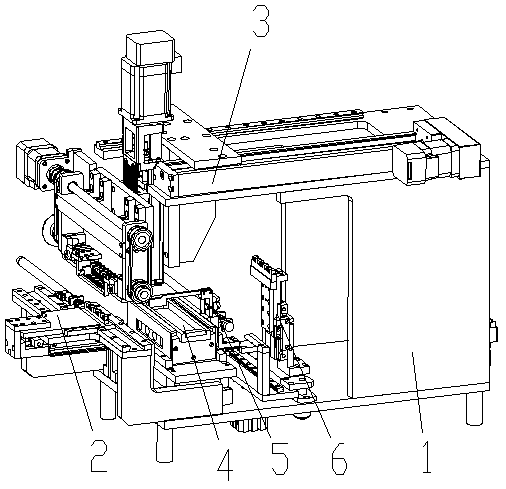
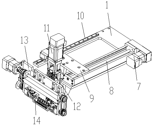
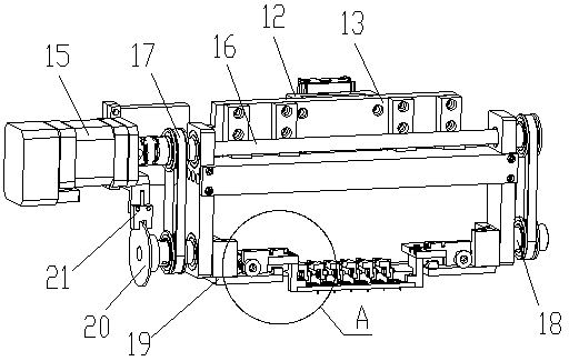
[0038] Such as Figure 1-Figure 6 As shown, the specific structure of the present invention is: a kind of automatic electroplating machine that can be used for the convenient clamping of irregular parts, it comprises frame 1, and the middle part of described frame 1 is provided with electroplating pool 4, and described electroplating pool The left side of 4 is provided with a feeding device 2 that cooperates with the carrier 33, and the carrier 33 is evenly provided with no less than two sets of socket columns that are socketed and matched with the product 26. The frame 1 The upper part is provided wit...


PUM


Abstract

The invention relates to an automatic electroplating machine capable of being used for irregular parts and facilitating clamping. The automatic electroplating machine comprises a rack. An electroplating pond is arranged in the middle of the rack. A feeding device cooperating with a carrier is arranged on the left side of the electroplating pond. At least two sets of sleeved connection columns in sleeved connection fit with products are evenly arranged on the carrier. A material taking mechanism cooperating with the feeding device is arranged on the upper portion of the rack. The material taking mechanism comprises a material taking moving device, a material taking lifting device arranged on the moving device and a material taking clamp which is arranged on the material taking lifting device and cooperates with the carrier. According to the automatic electroplating machine, the carrier is sleeved with the products, then the carrier enters a designated place through the feeding device, then the material taking clamp on the lower portion of the material taking mechanism is utilized for clamping and taking out all the products on the carrier, then the products fall into the electroplating pond to be electroplated through moving and lifting, the products are taken out after being electroplated, and meanwhile the feeding device completes feeding of the next carrier; and then electroplating continuity is greatly improved, and electroplating time is saved.

Description

[0001] Original application number: 2016112193305 [0002] Applicant of the original case: Dongguan Ronggong Automation Technology Co., Ltd. [0003] Date of original filing: December 26, 2016 [0004] Original application name: A simple automatic electroplating machine for sustainable electroplating. technical field [0005] The invention relates to the field of electroplating equipment, in particular to an automatic electroplating machine which can be used for convenient clamping of irregular parts. Background technique [0006] With the rapid development of electronic equipment, the demand for electronic products is increasing, and in the production and processing of electronic products, electroplating is mostly required, and electroplating is mostly done by electroplating machines. [0007] Most of the existing electroplating machines include an electroplating pool, and most of them directly clamp the product into the electroplating pool through tweezers for electropla...

Claims


Application Information

Patent Timeline
Patent Type & Authority Applications(China)
IPC IPC(8): C25D17/02C25D17/00C25D21/06C25D7/00
CPCC25D7/00C25D17/00C25D17/02C25D21/06
Inventor 邓君黄红梅
Owner 江门市美浩伦电镀有限公司
Why Eureka
Try Eureka