
Automatic oil suction device

A driving device and oil pumping technology, applied in the direction of measuring device, sampling device, sampling, etc., can solve the problems of affecting operation, low efficiency, prolonging oil pumping time, etc., and achieve the effect of preventing chronic diseases and high efficiency

Pending Publication Date: 2018-10-02
GUANGDONG POWER GRID CO LTD +1
View PDF9 Cites 1 Cited by
  • Summary
  • Abstract
  • Description
  • Claims
  • Application Information

AI Technical Summary

Problems solved by technology

[0003] There are many problems in extracting oil samples through the above method. 1. The test personnel will have more or less errors in oil extraction due to different people, or improper handling will lead to re-extracting samples; 3. When there are too many oil samples, the work of taking oil samples will take up most of the time, and the efficiency is low; 4. When oil pumping and testing are carried out at the same time, the test personnel will take the residual oil from their hands Bring it to various places of the test instrument, which will affect the subsequent operation; 5. During the process of extracting oil samples, the existence of air bubbles is often due to the existence of air bubbles. The existence of air bubbles will affect the results of the test. It is time-consuming to discharge the air bubbles, which prolongs the oil pumping. time

Method used


Image

  • Automatic oil suction device

Examples


Embodiment Construction

[0016] The present invention will be described in further detail below in conjunction with the accompanying drawings.

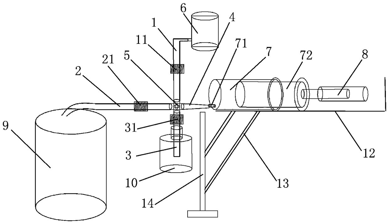
[0017] Such as figure 1 As shown, the present invention includes a four-way valve 5, the four ports of the four-way valve 5 are respectively connected with an air inlet pipe 1, a liquid discharge pipe 2, a sampling pipe 3 and a sampling pipe 4, and the air inlet pipe 1 is provided with a first A valve 11, and the outlet end of the inlet pipe 1 is connected with a carrier gas source 6, the discharge pipe 2 is provided with a second valve 21, and a waste liquid recovery container 9 is placed at the outlet of the discharge pipe 2 to recycle waste liquid, to avoid residual oil pollution, the sampling tube 3 is provided with a third valve 31, the outlet end of the sampling tube 4 is connected to the injection port 71 of the syringe 7, in order to ensure the tightness of the connection between the sampling tube 4 and the syringe 7, In this embodiment, the sampling...


PUM


Abstract

The invention discloses an automatic oil suction device which includes a four-way valve, of which the four mouths are respectively connected with a gas inlet pipe, a liquid discharge pipe, a samplingpipe and a sample suction pipe. A first valve is arranged on the gas inlet pipe; a carrier gas source is connected to the outlet end of the gas inlet pipe; a second valve is arranged on the liquid discharge pipe; a third valve is arranged on the sampling pipe; the outlet end of the sample suction pipe is connected to an injection port of an injector; a piston rod of the injector is connected to adriving apparatus which can drive the piston rod to move in a straight line reciprocating manner; a controller is connected to the driving apparatus so as to quantitatively control the moving distanceof the piston rod. In the device, the controller controls the driving apparatus so as to drive the piston rod of the injector to move, so that accurate quantitative suction can be completed and a test operator is free of directly contacting with the oil. The device can prevent chronic diseases and occupational diseases. If oil sample is excessive, the device can be operated in a parallel manner so as to reach high efficiency. With the carrier gas being cleaning gas, the device is free of influence on test results even bubbles exist in the device.

Description

technical field [0001] The invention belongs to the field of extraction devices for oil samples in chromatographic tests, and more specifically relates to an automatic oil extraction device. Background technique [0002] In the chromatographic test, the oil sample is usually taken back to the laboratory with a 125ml brown narrow-mouth bottle, and then the oil used for the test is pretreated. The tester manually extracts a 40ml oil sample, injects a certain amount of gas, and then puts it into a shock Shake in the instrument, and then do a pre-test on the obtained gas. [0003] There are many problems in extracting oil samples through the above method. 1. The test personnel will have more or less errors in oil extraction due to different people, or improper handling will lead to re-extracting samples; 3. When there are too many oil samples, the work of taking oil samples will take up most of the time, and the efficiency is low; 4. When oil pumping and testing are carried out...

Claims


Application Information

Patent Timeline
IPC IPC(8): G01N30/02G01N30/06G01N1/14
CPCG01N1/14G01N30/02G01N30/06G01N2001/1463
Inventor 刘伟胡志勇赖俊驹
Owner GUANGDONG POWER GRID CO LTD
Learn More