
Damping machine frame of microcomputer magnetic-actuation button attaching machine

A button sewing machine and microcomputer technology, applied in the direction of sewing clothes tools, etc., can solve the problems of easy damage of the shock absorption structure and poor shock absorption effect of the frame, so as to protect the buffer structure, improve the shock absorption efficiency, and ensure the shock absorption. shock effect

Inactive Publication Date: 2018-10-09
湖州三杰服饰有限公司
View PDF0 Cites 3 Cited by
  • Summary
  • Abstract
  • Description
  • Claims
  • Application Information

AI Technical Summary

Problems solved by technology

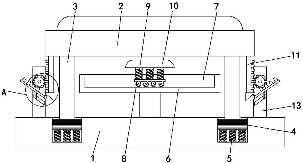
[0003] The purpose of the present invention is to solve the shortcomings in the prior art, such as: because the shock absorbing racks all perform shock absorbing in the same direction of the force, the shock absorbing effect of the rack is not good and the shock absorbing structure is easily damaged, while Proposed a shock-absorbing frame for microcomputer magnetic button sewing machine

Method used


Image

  • Damping machine frame of microcomputer magnetic-actuation button attaching machine
  • Damping machine frame of microcomputer magnetic-actuation button attaching machine

Examples


Embodiment Construction

[0017] The following will clearly and completely describe the technical solutions in the embodiments of the present invention with reference to the accompanying drawings in the embodiments of the present invention. Obviously, the described embodiments are only some, not all, embodiments of the present invention.

[0018] In describing the present invention, it should be understood that the terms "upper", "lower", "front", "rear", "left", "right", "top", "bottom", "inner", " The orientation or positional relationship indicated by "outside", etc. is based on the orientation or positional relationship shown in the drawings, and is only for the convenience of describing the present invention and simplifying the description, rather than indicating or implying that the referred device or element must have a specific orientation, so as to Specific orientation configurations and operations, therefore, are not to be construed as limitations on the invention.

[0019] refer to Figure ...


PUM


Abstract

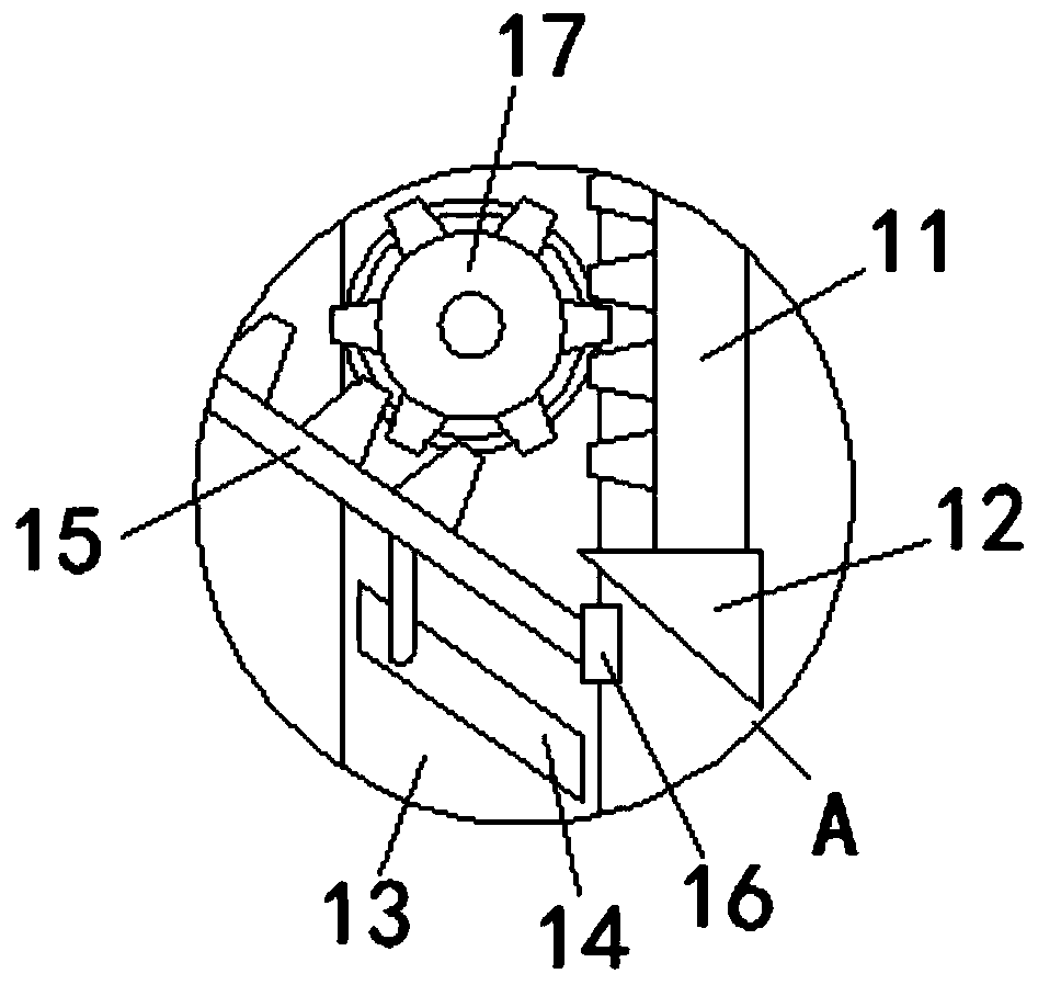
The invention discloses a damping machine frame of a microcomputer magnetic-actuation button attaching machine. The damping machine frame of the microcomputer magnetic-actuation button attaching machine comprises a base. The top of the base is provided with two symmetrical connecting grooves. A stress plate is installed above the base. The bottom of the stress plate is fixedly connected with two symmetrical support columns. The bottom ends of the two support columns are in inserted connection with the inner surfaces of the connecting grooves through a buffering piston. The bottom of the buffering piston is fixedly connected on the inner surfaces at the bottoms of the connecting grooves through a first spring. The top, through a connecting rod, of the base is fixedly connected with a bearing plate positioned between two support columns. The damping machine frame of the microcomputer magnetic-actuation button attaching machine is capable of, through installing a sliding chute and a connecting plate, performing a function of sliding unloading force on the inner surface of the sliding chute while a force unloading plate is extruded by the stress plate, through the sliding unloading force, avoiding a force unloading structure from being damaged by an impact force generated by vibration, and through the sliding unloading force, achieving an effect of guaranteeing a damping effect aswell as protecting a buffering structure in the greatest degree, thereby achieving an effect of long-term use conveniently.

Description

technical field [0001] The invention relates to the technical field of shock-absorbing racks, in particular to a shock-absorbing rack for a microcomputer magnetic button sewing machine. Background technique [0002] The full name is a rack server, which is used to fix the patch panels, casings and equipment in the telecommunications cabinet. It is usually 19 inches wide and 7 feet high. For the IT industry, it can be simply understood as a cabinet for storing servers. The shape does not look like Computers, like switches, have specifications such as 1U (1U=1.75 inches), 2U and 4U. Rack servers are installed in standard 19-inch cabinets and are functional servers. Therefore, the shock-absorbing rack of the microcomputer magnetic button sewing machine There are more and more applications, and the performance requirements for it are also increased. However, because the existing shock absorbing racks are all damped in the same direction of the force, the shock absorbing effect o...

Claims


Application Information

Patent Timeline
Patent Type & Authority Applications(China)
IPC IPC(8): A41H37/00
CPCA41H37/00
Inventor 邱国新
Owner 湖州三杰服饰有限公司
Learn More