All-terrain engineering vehicle model

An engineering vehicle and all-terrain technology, applied in toy vehicles, toys, entertainment, etc., can solve the problems of small motor output torque, inability to drive on rough roads, difficulty adapting to non-structural roads, etc., to improve power performance and save driving energy The effect of consuming and increasing the mileage

Inactive Publication Date: 2018-10-09
广州凯迪威文化股份有限公司广州分公司
0 Cites 2 Cited by

AI-Extracted Technical Summary

Problems solved by technology

[0002] All-terrain engineering vehicles generally use a crawler chassis to travel, and their power is generally driven by an engine, which has a high output power. For a highly simulated all-terrain engineering vehicle, its dri...

Method used

In the present embodiment, the driving gear of the fast shift gear pair 9 is engaged with the driving gear of the reduction gear pair 12 fixed on the first intermediate shaft 4 as the driven gear of the reduction gear pair 12, this ...

Abstract

The invention provides an all-terrain engineering vehicle model. The all-terrain engineering vehicle model comprises a vehicle body and a caterpillar-type chassis; the caterpillar-type chassis comprises a vehicle frame and a stepless speed change caterpillar-type driving system arranged on the vehicle frame; the stepless speed change caterpillar-type driving system comprises a driving motor, a caterpillar driving wheel, a caterpillar driven wheel, a caterpillar band which is in transmission cooperation with the caterpillar driving wheel and the caterpillar driven wheel, and a stepless speed changer used for transmitting power of the driving motor to the caterpillar driving wheel. By means of the all-terrain engineering vehicle model, stepless speed change can be achieved, so that the motorworks within an efficient working range all the time, and the driving force of the all-terrain engineering vehicle model is greatly increased.

Application Domain

Toy gearsToy vehicles

Technology Topic

TerrainVehicle frame +6

Image

  • All-terrain engineering vehicle model
  • All-terrain engineering vehicle model

Examples

  • Experimental program(1)

Example Embodiment

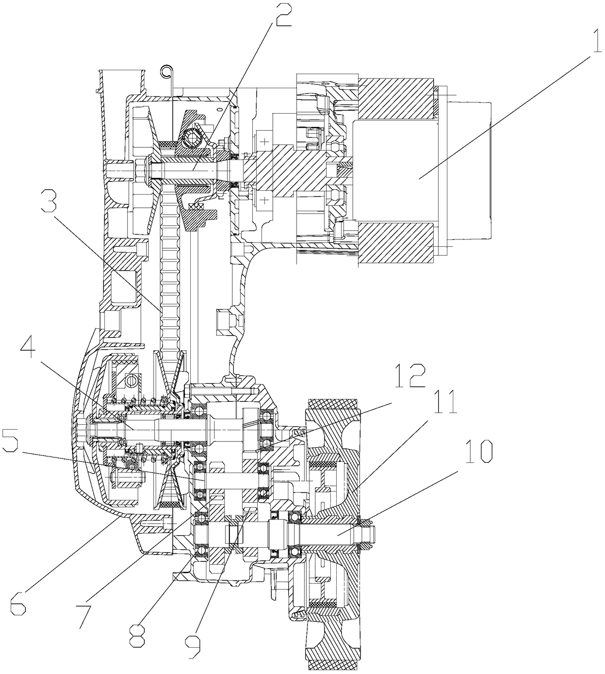
[0014] figure 1 It is a schematic structural view of the present invention, as shown in the figure, the all-terrain engineering vehicle model of the present invention includes a vehicle body 1 and a crawler chassis 14; the crawler chassis 14 includes a vehicle frame and a stepless Variable speed crawler drive system; the continuously variable crawler drive system includes a drive motor, a crawler driving wheel 14, a crawler driven wheel, a transmission that is matched to the crawler belt 16 of the crawler driving wheel 14 and a crawler guide wheel 17, and is used to drive the track driving wheel 14 and the track guide wheel 17 The power of the drive motor is transmitted to the continuously variable transmission of the track driving wheel 14;
[0015] The continuously variable transmission includes a housing 6, a first intermediate shaft 4 and a second intermediate shaft 5 that are rotatably supported in the housing 6 and are parallel to each other; the output shaft 2 of the driving motor 1 is passed through a metal belt The continuously variable transmission transmits power to the first countershaft 4; the first countershaft 4 transmits power to the second countershaft 5 through the reduction gear pair 12; At least two groups of shifting gear pairs transmit power to the wheel shaft 10 fixed to the track driving wheel 14; a synchronizer is arranged between the adjacent two groups of shifting gear pairs; the motor output shaft 2 and the first intermediate shaft 4 The existing steel belt type continuously variable transmission 3 is used to transmit power between the second intermediate shaft 5 and the vehicle axle 10, and a stepped speed change mechanism is used to transmit power between the second intermediate shaft 5 and the vehicle axle 10. The continuously variable transmission can automatically adjust the reduction ratio according to the driving resistance, so that the motor 1 Always work in a relatively high-efficiency working range, thereby saving driving energy consumption and increasing mileage; when the vehicle is driving on high-resistance road conditions such as uphill, and the maximum transmission ratio of the continuously variable transmission still cannot meet the power demand of the vehicle, it can be used The existing fork shift mechanism drives the synchronizer to act, so that a high transmission ratio shift gear pair is selected between the second intermediate shaft 5 and the wheel shaft 10, thereby improving the dynamic performance of the vehicle.
[0016] In the present embodiment, the shifting gear pairs are two groups, and are fast gear pairs 9 and slow gear pairs 7 respectively; , when the vehicle is running on a non-paved road or a large slope, the slow gear pair 7 is used for transmission to improve the dynamic performance of the vehicle.
[0017] In this embodiment, the driving gears of the fast gear pair 9 and the slow gear pair 7 are all driven and matched with the second intermediate shaft 5, and the driven gears of the fast gear pair 9 and the slow gear pair 7 can be The synchronizer is matched with the wheel shaft 10 in rotation; the synchronizer is matched with the wheel shaft 10 in the manner of axial sliding and circumferential transmission.
[0018] In this embodiment, an axle seat 8 for rotatably supporting the axle 10 is formed in the housing 6; the axle 10 is rotatably supported in the axle seat 8 through a bearing. The axle seat 8 is separately fixedly installed on the vehicle frame. In this embodiment, the axle seat 8 is directly arranged in the casing 6 of the transmission, which can further simplify the structure of the vehicle.
[0019] In this embodiment, the driving gear of the fast gear pair 9 is used as the driven gear of the reduction gear pair 12 to mesh with the driving gear of the reduction gear pair 12 fixed on the first intermediate shaft 4. This arrangement makes the speed reduction The driven gear of the gear pair 12 is used as the driving gear of the fast gear pair 9 at the same time, which reduces the number of parts of the system and reduces the manufacturing cost.
[0020] Finally, it is noted that the above embodiments are only used to illustrate the technical solutions of the present invention without limitation. Although the present invention has been described in detail with reference to the preferred embodiments, those of ordinary skill in the art should understand that the technical solutions of the present invention can be carried out Modifications or equivalent replacements without departing from the spirit and scope of the technical solution of the utility model shall be covered by the scope of the claims of the present invention.

PUM

no PUM

Description & Claims & Application Information

We can also present the details of the Description, Claims and Application information to help users get a comprehensive understanding of the technical details of the patent, such as background art, summary of invention, brief description of drawings, description of embodiments, and other original content. On the other hand, users can also determine the specific scope of protection of the technology through the list of claims; as well as understand the changes in the life cycle of the technology with the presentation of the patent timeline. Login to view more.

Similar technology patents

Intelligent air outlet system and method and vehicle

Owner:ZHEJIANG GEELY HLDG GRP CO LTD +1

Vehicle centroid adjustment structure

InactiveCN107458504Aincrease mileageHigh energy saving rate
Owner:尚书

Photovoltaic energy electric vehicle

PendingCN113682148AEnergy saving and environmental protection mileageIncrease mileage
Owner:江艳

Motor and electric vehicle with same

InactiveCN112072839AExtended gliding distanceincrease mileage
Owner:王伟

Classification and recommendation of technical efficacy words

  • Increase mileage

Heat pump system for vehicle

ActiveUS20150217625A1increase mileageelectric power consumption
Owner:HANON SYST

Braking energy recovery control method and device and electromobile

ActiveCN105599616AImprove energy recoveryIncrease mileage
Owner:BEIJING ELECTRIC VEHICLE

Heating management system for hybrid vehicle

Owner:奇瑞新能源汽车股份有限公司

Pure electric automobile as well as control method and control device for cooling system thereof

ActiveCN108297677AOptimize Energy Efficiency RatioIncrease mileage
Owner:国机智骏汽车有限公司
Why Eureka
Try Eureka