I-steel overturning welding device

A technology for welding devices and I-beams, which is applied in the direction of auxiliary devices, welding equipment, auxiliary welding equipment, etc., can solve the problems of heavy workload, low efficiency and troublesome turning methods, and achieve improved efficiency, simplified operation, and improved turning efficiency Effect

Inactive Publication Date: 2018-10-09
宜昌众友机械有限公司
View PDF0 Cites 6 Cited by
  • Summary
  • Abstract
  • Description
  • Claims
  • Application Information

AI Technical Summary

Problems solved by technology

[0002] During the processing of the I-beam, two flanges and one web need to be welded, and four welding operations are required. In the existing processing process, after the joints on the same side are welded, the workpiece is manually welded. Turn over and then perform subsequent welding operations. This way of turning over is inefficient and requires a lot of work. After manual turning, it is necessary to align the workpiece with the welding torch, which is very troublesome.

Method used


Image

  • I-steel overturning welding device
  • I-steel overturning welding device

Examples


Embodiment Construction

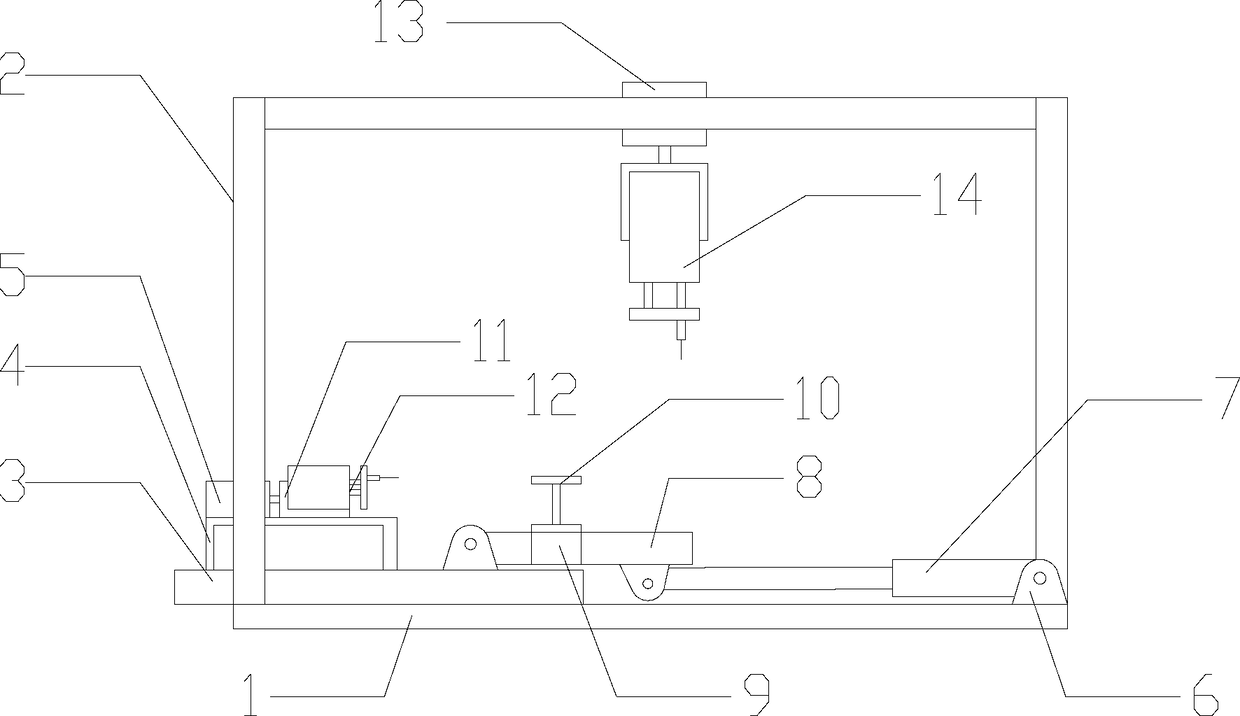
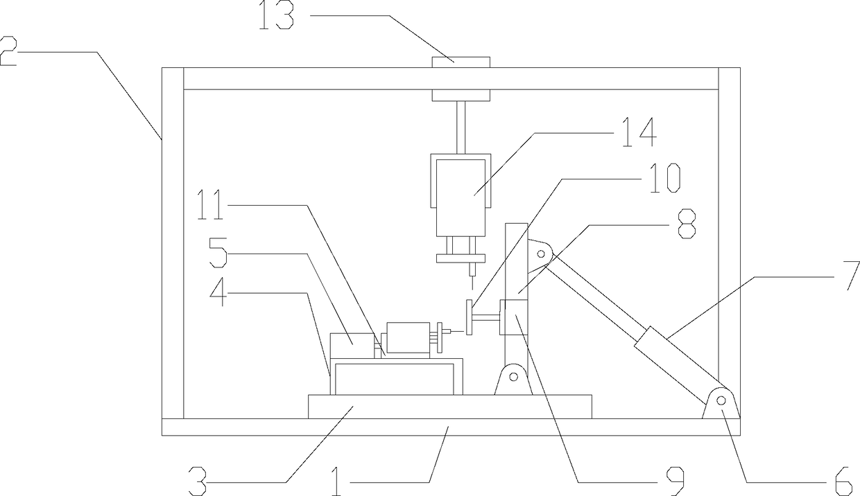
[0017] As shown in the figure, an I-beam turning welding device includes a base 1, a door frame 2 is provided on the base 1, a motor 6 is provided on one side of the base 1, one end of the telescopic rod 7 is fixed on the motor 6, and the other side of the base 1 A sliding seat 3 is provided on the top, and the sliding seat 3 can slide toward the direction of the motor 6 on the base 1. The sliding seat 3 is provided with a support 4, and the support 4 is fixed with a first hydraulic cylinder 5, and the first hydraulic cylinder 5 is fixed on the support 4. The push rod of the cylinder 5 is provided with a welding torch holder 11, the welding torch holder 11 is provided with a first welding torch 12, and the first welding torch 12 faces the direction of the motor 6 horizontally;

[0018] The door frame 2 is provided with a second hydraulic cylinder 13, the push rod of the second hydraulic cylinder 13 is vertically downward, and the push rod is provided with a second welding torch...


PUM


Abstract

An I-steel overturning welding device comprises a base on which a door frame is arranged, wherein a motor is arranged at one side of the base; one end of a telescoping rod is fixed to a motor; a sliding seat is arranged on the other side of the base, and the sliding seat can slide on the base in the direction toward the motor; a supporting seat is arranged on the sliding seat, and a first hydraulic cylinder is fixed to the supporting seat; a welding gun fixing seat is arranged on a pushing rod of the first hydraulic cylinder, and a first welding gun is arranged on the welding gun fixing seat and is horizontally positioned in the motor direction; a second hydraulic cylinder is arranged on the door frame, and a pushing rod of the second hydraulic cylinder is vertically downward; a second welding gun is arranged on the pushing rod; a working plate is arranged on the sliding seat; on end of the working plate is hinged with the top surface of the sliding seat; and one end, far away from themotor, of a telescoping rod is hinged with the bottom surface of the working plate. According to the device adopting the abovementioned structure, an I-steel can be automatically welded during welding processing, and moreover, the accuracy of a welding position is ensured, so that the welding efficiency is improved, and meanwhile, the welding quality is ensured.

Description

technical field [0001] The invention relates to the field of steel structure production and processing, in particular to an I-beam overturn welding device. Background technique [0002] During the processing of the I-beam, two flanges and one web need to be welded, and four welding operations are required. In the existing processing process, after the joints on the same side are welded, the workpiece is manually welded. Turning over and then performing subsequent welding operations, this turning method is inefficient and has a large workload. After manual turning, it is necessary to align the workpiece with the welding torch, which is very troublesome. Contents of the invention [0003] The technical problem to be solved by the present invention is to provide an I-beam turning welding device, which realizes the automatic welding in the I-beam welding process, and ensures the accuracy of the welding position, which not only improves the welding operation efficiency, but als...

Claims


Application Information

Patent Timeline
Patent Type & Authority Applications(China)
IPC IPC(8): B23K37/047
CPCB23K37/047
Inventor 李长青
Owner 宜昌众友机械有限公司
Why Eureka
Try Eureka