Automatically-controlled pneumatic cyclone supercharger

A supercharger and pneumatic technology, which is applied in the field of swirl booster and self-control pneumatic swirl booster, can solve the problem of weak swirl strength, large loss of turbulent energy, and cannot be used in the occasions where materials pass through pipeline transportation, etc. problem, to achieve the effect of reducing energy consumption

Inactive Publication Date: 2018-10-09
CHINA UNIV OF MINING & TECH
View PDF4 Cites 0 Cited by
  • Summary
  • Abstract
  • Description
  • Claims
  • Application Information

AI Technical Summary

Problems solved by technology

[0003] The cyclone is the key component of the pneumatic conveying of the vortex flow. It is used to generate the vortex flow field. It often adopts the forms of radial pulse swirl blades, tangential air intake and spiral pipe wall, but the above-mentioned methods all have shortcomings. Where the radial pulse swirl vanes can generate a strong vortex airflow, but there are vanes in the middle, which cannot be used in the occasions where materials pass through the pipeline, and are generally only used at the air inlet position; the tangential air intake method is more suitable for occasions Wide, but the loss of turbulent energy is large, and once the structure is determined, the strength of the vortex flow field and the distribution of air velocity are not easy to adjust; the spiral pipe wall can be used in the occasions where materials pass through the pipeline, but the vortex intensity is weak and the air velocity distribution is weak. It is completely determined by the pipe wall structure, so it has certain limitations
In general, the existing swirl pneumatic conveying devices have problems such as rapid swirl strength weakening and large energy consumption.

Method used


Image

  • Automatically-controlled pneumatic cyclone supercharger
  • Automatically-controlled pneumatic cyclone supercharger
  • Automatically-controlled pneumatic cyclone supercharger

Examples


Embodiment Construction

[0023] The present invention will be described in detail below in conjunction with the accompanying drawings.

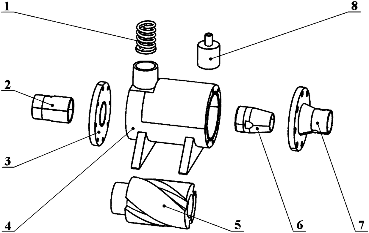
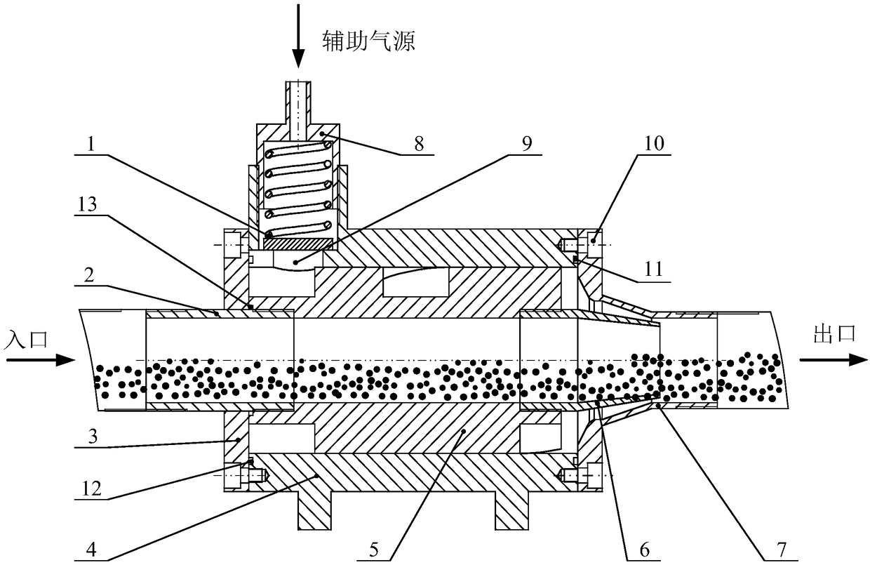
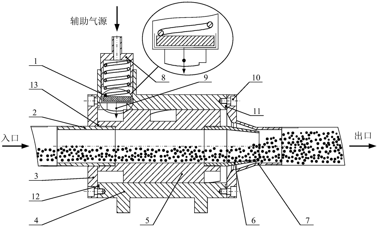
[0024] Such as Figure 1 to Figure 3 As shown, a self-control pneumatic swirl supercharger includes a housing 4, an air intake pipeline and an air outlet pipeline. There is an auxiliary air source inlet 9 on the side wall of the housing 4, and there is also a swirl vane 5 inside the housing 4. The swirl vane 5 is cylindrical, and its side wall is provided with a spiral guide groove along the axial direction. , the air inlet end of the swirl vane 5 has a stepped surface; the through hole provided at the auxiliary air source inlet 9 on the side wall of the housing 4 is a T-shaped hole, and its inner wall is provided with an internal thread, and the auxiliary air source inlet is The valve adjusting bolt 8 is installed through the thread, the upper end of the valve adjusting bolt 8 has an air intake through hole, and the lower end has a cylindrical inner cavity, and a c...


PUM


Abstract

The invention discloses an automatically-controlled pneumatic cyclone supercharger. The automatically-controlled pneumatic cyclone supercharger comprises a shell, an air inlet pipeline and an air outlet pipeline, wherein a cyclone vane is arranged in the shell; an air valve adjustment bolt is mounted on an air inlet of an auxiliary air source through threads; an air inlet through hole is formed inthe upper end of the air valve adjustment bolt; a cylindrical inner cavity is formed in the lower end of the air valve adjustment bolt; a compression spring with a pressing plate at the bottom is received in the cavity; the area of the pressing plate is greater than the area of an air inlet hole in the lower end of the air inlet of the auxiliary air source on the shell; an air inlet adjustment pipe is arranged on an air inlet pipeline, is connected with a main conveying pipeline in series through a pipe connector and is in threaded connection with the left end of the inner wall of the cyclonevane; an air outlet adjustment pipe is arranged on an air outlet pipeline and is in threaded connection with the right end of the inner wall of the cyclone vane. The automatically-controlled pneumatic cyclone supercharger is wide in application range and is capable of automatically controlling the airflow of the auxiliary supplement air, reducing the energy consumption caused by the air source and simultaneously reducing pipeline abrasion, reducing particle breakage and avoiding pipeline blockage.

Description

technical field [0001] The invention relates to a swirl supercharger, in particular to a self-control pneumatic swirl supercharger, which belongs to the technical field of pneumatic conveying equipment. Background technique [0002] Pneumatic conveying, also known as air conveying, is to use the energy of high-speed airflow to realize short-distance conveying of granular materials along the airflow direction in a closed pipeline, and it is a specific application of fluidization technology. Pneumatic conveying device is simple in structure, easy to operate, and can be used for horizontal, vertical or inclined conveying. At present, horizontal and axial pneumatic conveying is often used, which has the advantages of cleanliness, environmental protection and safety, but it also has the advantages of large power consumption and easy Disadvantages such as material crushing and pipeline blockage occur. In order to improve the above shortcomings of the horizontal axial pneumatic co...

Claims


Application Information

Patent Timeline
IPC IPC(8): B65G53/66B65G53/16
CPCB65G53/66B65G53/16
Inventor 纪云刘送永江红祥李伟沈刚唐玮
Owner CHINA UNIV OF MINING & TECH
Why Eureka
Try Eureka