Microfluidic device

A technology of microfluidic device and microfluidic chip, which is applied in liquid displacement machinery, machine/engine, pump with flexible working elements, etc. It can solve problems such as large unit area, increased processing difficulty, and influence on control accuracy. , to achieve the effect of reducing processing difficulty, facilitating separate processing, and avoiding direct contact

Active Publication Date: 2020-01-31
UNIV OF SCI & TECH OF CHINA
View PDF1 Cites 0 Cited by
  • Summary
  • Abstract
  • Description
  • Claims
  • Application Information

AI Technical Summary

Problems solved by technology

[0004] However, the structure of the above-mentioned microfluidic device is relatively complicated, such as the peristaltic micropump in which the piezoelectric actuator and the substrate are integrated in the integrated piezoelectric peristaltic micropump, the structure and manufacturing process are complicated, which increases the difficulty of processing; and, the piezoelectric The unit area formed by the actuator and the base body is too large, resulting in a large volume of the cavity, which cannot accurately control the transportation of trace liquids and affects the control accuracy

Method used


Image

  • Microfluidic device
  • Microfluidic device
  • Microfluidic device

Examples


Embodiment Construction

[0035] The invention discloses a microfluidic control device to reduce processing difficulty and improve control precision.

[0036] The following will clearly and completely describe the technical solutions in the embodiments of the present invention with reference to the accompanying drawings in the embodiments of the present invention. Obviously, the described embodiments are only some, not all, embodiments of the present invention. Based on the embodiments of the present invention, all other embodiments obtained by persons of ordinary skill in the art without making creative efforts belong to the protection scope of the present invention.

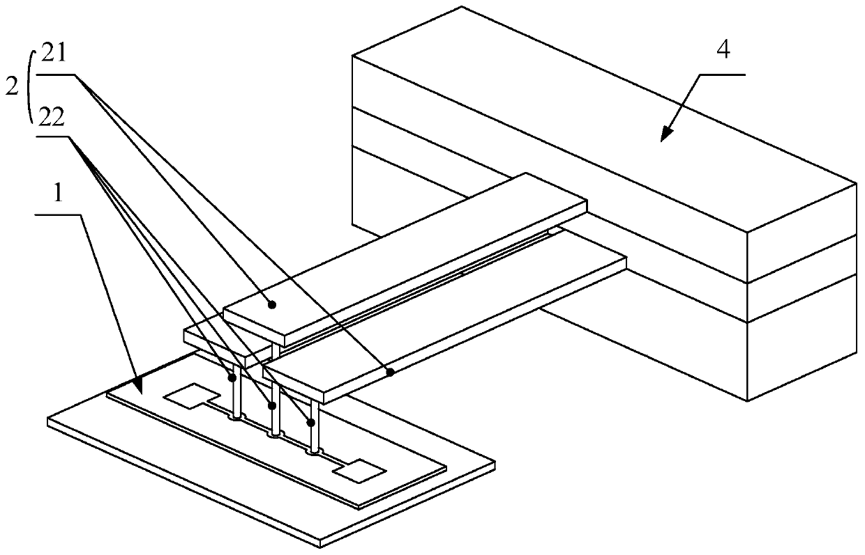
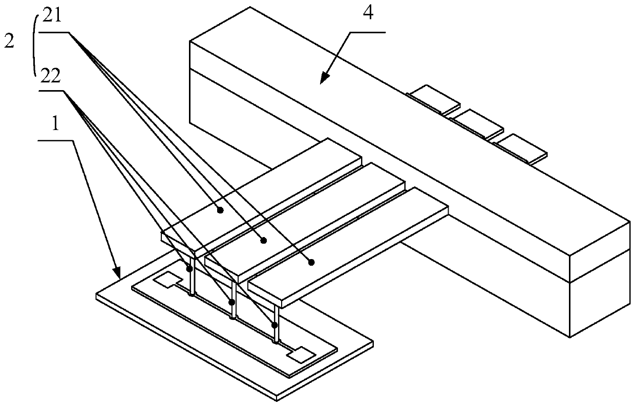
[0037] Please refer to figure 1 and figure 2 , figure 1 The first structural schematic diagram of the microfluidic device provided by the embodiment of the present invention; figure 2 A schematic diagram of the second structure of the microfluidic device provided by the embodiment of the present invention.

[0038] An embodiment o...


PUM


Abstract

The invention discloses a micro-fluidic device. The micro-fluidic device comprises a displacement actuator (2) and a micro-fluidic chip (1); the displacement actuator (2) and the micro-fluidic chip (1) are mutually independent; the micro-fluidic chip (1) is provided with a micro-pipeline; the micro-pipeline is provided with an input end (11) and an output end (12); an extruding part (13) is arranged between the input end (11) and the output end (12) of the micro-pipeline; and the displacement actuator (2) is provided with a brake part for extruding the micro-pipeline of the extruding part (13). According to the micro-fluidic device provided by the invention, the displacement actuator and the micro-fluidic chip are mutually independent, so that separate processing of the displacement actuator and the micro-fluidic chip is facilitated and the processing difficulty of the overall manufacturing process is reduced; and the condition that fluid is directly contacted with the displacement actuator is effectively avoided, the fluid flows only through the micro-pipeline, the flow area of the fluid is controlled conveniently and the control precision is improved.

Description

technical field [0001] The invention relates to the technical field of microfluidic equipment, in particular to a microfluidic device. Background technique [0002] Microfluidic devices refer to devices that use microchannels or microstructures to process or manipulate tiny fluids. Taking the micro peristaltic pump in the microfluidic device as an example, it is the pump body that drives the fluid flow in the micropipe. Among them, there are many structures that drive fluid flow. [0003] Among the current miniature peristaltic pumps, some are driven by piezoelectric pumps integrated on the chip. For example, the document Journal of Physics D: Applied Physics, 2016, 49, 175402 introduces a time-phase-shift peristaltic micropump for research. pump system. There is also an electrostatically driven peristaltic micropump on an integrated chip, such as the document Lab on a Chip, 2004, 4, 495-501, which introduces an electrostatically driven micro peristaltic pump on a chip. ...

Claims


Application Information

Patent Timeline
Patent Type & Authority Patents(China)
IPC IPC(8): F04B43/12F04B17/03
CPCF04B17/03F04B43/12
Inventor 李保庆禇家如马托
Owner UNIV OF SCI & TECH OF CHINA
Why Eureka
Try Eureka