
Special gear assembly connecting shaft

A technology of gear connection and shaft connection, which is applied in the direction of belt/chain/gear, shaft, shaft and bearing, etc. It can solve the problems of poor connection tightness, shortened gear structure life, and affecting the normal use of the gear structure, etc.

Inactive Publication Date: 2018-10-09
丁涌
View PDF0 Cites 0 Cited by
  • Summary
  • Abstract
  • Description
  • Claims
  • Application Information

AI Technical Summary

Problems solved by technology

The traditional gear structure is assembled and connected through the central connecting shaft during assembly and use, but the connection structure of the traditional connecting shaft is relatively simple, and the stability of the connection is relatively poor, and the gear structure is due to the mutual meshing between the teeth during use. Wear will occur between the gear structures, and relatively large heat will be generated at the position where the connecting shaft is assembled in the center of the gear structure. These will have a certain impact on the gear structure, shorten the life of the gear structure, and damage the gear structure in severe cases. affect its normal use
During the long-term use of the gear structure, the tightness of the connection between it and the gear connecting shaft will deteriorate after long-term use. In some application environments with relatively high vibration frequencies, it may cause loose assembly and affect the normality of the gear structure. use

Method used


Image

  • Special gear assembly connecting shaft
  • Special gear assembly connecting shaft
  • Special gear assembly connecting shaft

Examples


Embodiment Construction

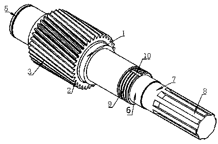
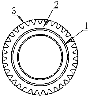
[0016] Such as Figure 1 to Figure 5 As shown in the figure, a special gear assembly connecting shaft is mainly engaged with the helical gear structure when used. Its structural strength is relatively high, and its structural stability is more reliable in the process of adjusting and rotating, and its service life is longer. Longer, the connecting shaft is provided with an anti-loose fastening connecting column on the connecting shaft, and a threaded anti-loose fastening structure is set on the anti-loose fastening connecting column, so that it can be better connected with mechanical equipment during assembly. At the same time, the safety of this part and the gear structure is higher, and the firmness of the connection is more reliable. During assembly, the anti-loosening positioning groove provided on the structure can make the accuracy of the assembly position higher, and the assembly is more accurate. It is convenient, so that it can rotate better during use, and the helica...


PUM


Abstract

The invention relates to the technical field of gear assembly structures, in particular to a special gear assembly connecting shaft. According to the adopted technical scheme, the special gear assembly connecting shaft comprises a cylindrical body gear connection column, and the outer cylinder face of the body gear connection column is provided with a cylindrical bevel gear column body structure;the distance from the left side end face of the bevel gear column body structure to the left side end face of the body gear connection column is equal to the distance from the right side end face of the bevel gear column body structure to the right side end face of the body gear connection column; the outer cylinder face of the bevel gear column body structure is provided with bevel gear tooth structures which are uniformly distributed around the circumference; the left and right side end faces of the bevel gear tooth structures coincide with the left and right side end faces of the bevel gearcolumn body structure correspondingly; and the center position of the left and right side end faces of the bevel gear column body structure are each provided with an integrally formed cylindrical connecting and supporting column. The special gear assembly connecting shaft has the beneficial effects that the structural strength is high, in the adjusting, rotating and using process, the structuralstability is more reliable, and the service life is longer.

Description

technical field [0001] The invention relates to the technical field of gear assembly structures, in particular to a special gear assembly connecting shaft. Background technique [0002] A gear is a mechanical element with teeth on the rim that can continuously mesh to transmit motion and power. It is a toothed mechanical part that can mesh with each other. The traditional gear structure is assembled and connected through the central connecting shaft during assembly and use, but the connection structure of the traditional connecting shaft is relatively simple, and the stability of the connection is relatively poor, and the gear structure is due to the mutual meshing between the teeth during use. Wear will occur between the gear structures, and relatively large heat will be generated at the position where the connecting shaft is assembled in the center of the gear structure. These will have a certain impact on the gear structure, shorten the life of the gear structure, and dam...

Claims


Application Information

Patent Timeline
IPC IPC(8): F16H55/17F16C3/02
CPCF16H55/17F16C3/02
Inventor 丁涌
Owner 丁涌
Learn More